
3D Molding Simulation Growing in Accuracy & Capabilities
New developments in 3D simulation can handle processes like gas assist, coinjection, and multi-shot molding and add features like birefringence prediction.

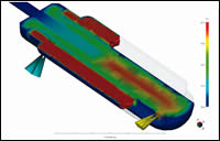
Insert molding and two-shot overmolding—both shown in this screwdriver handle—are helping to increase the use of 3D analysis. (Photo: Moldflow)
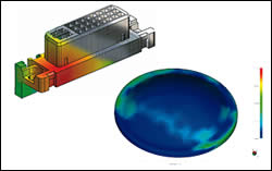
3D simulation reportedly is better able to model thin-wall parts with complex geometries such as the connector above (modeled in Moldex3D from CoreTech). 3D can also deliver new capabilities that 2.5D analysis cannot, such as predicting birefringence in optical lenses (as in Moldflow’s MPI 6.1).
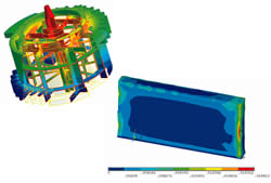
3D software from Sigma is now able to predict where features like rings and undercuts in the mold can restrict free shrinkage of a part and build up stresses.
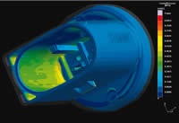
Some newer capabilities from 3D software suppliers include improved ability to model hot runners or flow imbalances in multi-cavity filling (shown at left in Vero’s Visi-Flow), or generating stress or fiber-orientation data that more easily integrates with FEA structural analysis packages (an example being CoreTech’s Moldex3D at right).
So-called 3D injection molding simulation—using a mesh of 3D solid elements—used to be applicable to only about 5% of simulation applications that involved thick, chunky parts that did not lend themselves to conventional thin-shell 2.5D analysis. But 3D is now branching out to cover more types of molding and to more tightly integrate simulation data with structural design analysis. Software suppliers are bringing over capabilities for analyzing gas assist, coinjection, multi-shot and insert molding, and use of stack or family molds from 2.5D programs to the newer 3D platforms. “All our simulation capabilities are now available in 3D, and some of the newest developments are only in 3D,” says a Moldflow spokesman.
Analyzing complex molding processes has been improved with better abilities to model heat transfer between different materials. Other recent developments for 3D software improve predictions of residual stress in a part that can affect optical properties, warpage, and mechanical strength.


Growing need for 3D
Suppliers of 3D simulation technology—including CoreTech, Moldflow, Sigma Engineering, and Vero International—agree that only 5% to 10% of injection molded parts are ideally suited to 3D simulation, while the rest can be analyzed satisfactorily with 2.5D “shell” technology or Moldflow’s related Dual Domain approach. But suppliers say use of 3D analysis is set to expand. They claim that not only are plastic parts growing more complex, but users are looking to apply 3D simulation to parts already being analyzed with 2.5D technology, even though 3D analysis consumes more time and memory. That’s why 3D analysis is where most of the news is in mold simulation, even though it is still a small part of the total market.
“3D simulation allows the molder or mold designer to streamline the entire modeling process. They can take the 3D CAD file directly, unlike 2.5D programming, which requires conversion of the original file to a midplane model—and problems can arise in doing so. Also, the results from 3D simulation can more readily be exported into structural analysis packages,” says Venny Yang, president of CoreTech International.
Moldflow sources note that the firm’s proprietary Dual Domain simulation is similar to 2.5D but requires no conversion to a midplane model. However, Moldflow’s product line manager Murali Annareddy agrees with Yang’s second point about easier conversion from 3D simulation to structural analysis: “Mechanical design engineers want better interfaces between plastics and structural CAE analysis so they can perform more accurate structural analyses while taking into account predictions of molded-in stresses and fiber orientation.”
3D simulation can take into account more than just planar flow—it can model turbulent and laminar flow, jetting, air pockets or bubbles in the melt, and the effects of gravity. It also allows for modeling parts with non-uniform wall thicknesses. “These days very few parts are designed with uniform wall thickness,” says Natalia Kassa, consultant at Vero International. “More assumptions have to be made with 2.5D, and if that assumption is incorrect it will generate erroneous results. The 2.5D approach for complex parts with variable thickness requires advanced knowledge of rheology and experience to interpret those transitions in wall thickness correctly. As a result, some areas of the simulation model may look quite different from the part it represents in order to provide correct results,” she says.
“The biggest complaint of 2.5D users is that it can give you reasonable flow, pack and cool, but it falls short on predicting warpage. Predicting warpage and shrinkage at a higher level is a trend,” adds CoreTech’s Yang.
Optical parts are a growing area for plastics molding and have focused the attention of 3D software suppliers. Users looking to convert from glass to plastic face the critical need to minimize orientation and residual stresses in order to reduce distortion of light travel. Moldflow, CoreTech, and Sigma have developed or are working on this emerging area of birefringence. Another hot area for 3D simulation is multi-material molding, which is growing in popularity but has been a challenge for 2.5D software to emulate its complexities.
New analysis features
As an example of extending the capabilities of 3D simulation software, Moldflow includes what it calls a “breakthrough” innovation in its latest Moldflow Plastics Insight (MPI) version 6.1 package. A new add-on option to its 3D warpage module predicts flow-induced stresses and resulting birefringence (double-refraction) defects in optical parts such as automotive lighting, magnifying lenses for inspecting medical x-rays, cell-phone display screens, and other lenses. It can model six plastic materials that have so far been tested for optical properties.
Moldflow also recently developed a new use of molding simulation to evaluate injection machine performance. Its new nozzle-pressure prediction can generate a more accurate picture of melt flow and shear heating. Simulating pressure at the nozzle can also be used with ram position and the injection-speed profile to determine filling time and test whether equipment such as a check valve is functioning properly or is faulty or worn. The pressure sensor may even give insight into material drying, which can affect melt viscosity and resulting injection pressure, says Moldflow’s Annareddy.
What’s more, molders can simulate air-shot pressure to determine pressure losses between the barrel and sprue tip. The simulation can be used as a guide to determine melt compressibility by comparing machine hydraulic pressure to measured nozzle pressure. More accurate determination of melt pressure improves prediction of core deflection, packing, and warpage.
In the past 18 months, Moldflow enhanced its 3D flow simulation with the ability to predict partial remelting of the interface zone during overmolding of one plastic with another. The software alerts the user to the possibility of smearing the first material into the second. Also, the software can predict air traps or pockets deep within a thin-shell part as well as on the surface.
Moldflow released a new product that allows users of Ansys and Abaqus structural analysis programs to easily import simulation results from both its Moldflow Plastics Insight (MPI) 3D simulation software and its Moldflow Plastics Advisers (MPA) validation tool (which gained 3D capability just this year). The new Moldflow Structural Alliance (MSA 1.0) uses mapping technology that creates a mesh-independent link between molding simulation and structural analysis models. Structural analysis software typically assumes plastic parts have consistent material properties throughout, but the flow pattern of molten plastic and orientation of fiber reinforcements introduce variations that affect the structural performance of the part. MSA enables structural analysis programs to account for these variations in order to provide more realistic results.
Moldflow also recently created a new pricing and licensing approach, called MPI Enterprise, designed to make it more economical for more users to perform more kinds of analyses more often. Its new “task-based” licensing is no longer based on the number of users (or “seats”) at a customer. Multiple users can access the software for the same price. Also, there is no longer an extra charge to update from 2.5D to Dual Domain or 3D technology—the user can choose the appropriate analysis geometry for any task because all are included in the “bundle” purchased. These bundles also make it dramatically more economical to perform advanced analyses compared with the former approach of buying individual modules.
MPI Enterprise offers a “Standard” platform of basic flow and packing simulation programs that even the smallest company can afford. It’s “Performance” platform adds modules for cooling, shrinkage, warpage, and fiber orientation. Its “Process Extension” platform also bundles specialty modules such as gas-assist, coinjection, injection-compression, birefringence, thermoset, MuCell microcellular foaming, and other advanced molding modules.
Software evolution
Vero International, a supplier of 3D CAD/CAM software for mold and die makers, has expanded its suite to include injection molding simulation. Last September, Vero acquired Plastics & Computer of Italy and its simulation tools that include numerical cost and production optimization solutions and 2.5D and 3D simulation modules. The 3D modules, which cover process simulation from filling through cooling and warpage analysis, as well as fiber orientation, make up Vero’s new Visi-Flow product line.
Visi-Flow uses proprietary hybrid meshing technology. Traditional shell meshing requires a long model preparation time, while 3D solid meshing imposes long calculation time. Visi-Flow produces an external shell mesh and automatically creates an internal hexahedral mesh. This makes it possible to achieve the accuracy of 3D solid analysis with very short calculation times typical of the shell approach, Kassa says.
Vero expects to introduce a gas-assist module for its 3D package next month. Modeling the gas in 3D solids is much less of a challenge than in 2.5D, notes Kassa, because gas-assisted parts have a combination of different thicknesses. “The gas channel can be 10 times thicker than the nominal plastic wall, which can have differential thicknesses through a cross-section,” she notes. Vero is also working on moving all its 2.5D programs into solids-based 3D, including coinjection, two-shot, and thermoset molding.
Focus on heat transfer
Several new features and enhancements are included in the newly released Moldex3D version 8.1 from CoreTech System Co. Ltd. in Taiwan, and more new capabilities are promised in its upcoming 9.0 release. For example, new birefringence software will help predict flow-induced stresses in optical parts. Moldex3D software for Windows and Linux is offered in the U.S. exclusively through EPS Flotek.
Highlights of the newest version include shorter computation times, support of multi-component injection processes such as insert and two-shot molding, and improved fiber-orientation calculation. CoreTech has also improved the interfacing of simulation results with FEA structural analysis programs such as Ansys and Abacus. Research continues on better modeling of gas and water assist.
Thermal issues were of primary importance in developing the latest Moldex3D software, says CoreTech’s Yang. A new SolidCool function can better simulate mold surface-temperature variations over time, he says. A new Rapid Heating Cooling Molding (RHCM) module models cycling the mold temperature from hot to cold over the course of a molding cycle. Unlike the standard approach of maintaining constant mold temperature, RHCM simulates the results of deliberately using higher mold temperature during filling and packing and then dropping the temperature for the remainder of cycle. “In most cases, molders want a lower mold temperature to reduce cycle time, but a lower mold temperature can produce a weld line and negatively affect part surface quality,” explains Yang. “Some molders raise the mold temperature at the expense of lengthening cycle times.” He says the best of both worlds can be accomplished by using a cavity pressure sensor to switch from higher to lower mold temperature.
CoreTech has also retooled its system software to calculate fiber orientation 1.5 times to about 30 times faster, depending on model size. Warpage prediction is also said to run faster.
Moldex3D software can be used to model the in-mold decoration process. “With 3D you can see what is happening to the decorated part from all directions, whereas a 2.5D program will assume the effects of heat conduction, cooling, and warpage,” says Yang.
For the next version of the software, Yang says CoreTech has developed a special module for multi-component molding that models the part with a metal or plastic insert and considers the effects of cooling and heat conduction. It can also take mechanical properties of both materials into consideration for prediction of warpage.
A new eDesign module that is part of Moldex3D 8.1 is an easy-to-use solid-modeling program for thick or thin part validation that takes a 3D CAD geometry to analysis results in a few simple steps. Somewhat like Moldflow Plastic Advisers, eDesign is for molders looking to check the part or mold design quickly. Users can optimize gate locations, prevent short shots and weld lines, evaluate cooling circuits, and minimize cycle times.
Best of all, users spend no time preparing the model. The eDesign software can generate a 2.5D mesh directly from 3D CAD file with a single keystroke. Users can specify the level of meshing control to balance calculation time versus simulation accuracy. eDesign then carries out 3D flow, packing, cooling, and warpage analyses (and fiber orientation if required) using the same 3D solver technology as CoreTech’s 3D solid program. Software “wizards” help to speed data entry and program operation. eDesign automatically selects the mesh elements for the surface and cross-section of the part and generates a mesh even for a complicated 3D geometry within 15 to 20 min.
Hot-runners and more
Hot-runner simulation is among the newest capabilities added to version 4.5 of 3D-Sigma from Sigma Engineering. The software can import the hot-runner’s heater geometry as well as its heat capacity and thermal conductivity as a function of temperature. Sigma also claims an industry first in the ability of this software to simulate the electrical wattage delivered to the ends of the heaters, by mimicking the temperature distribution in the heater and simulating the subsequent heat flow from the heater into the bushing and from the bushing into the melt in the hot-runner channel.
Sigma claims another breakthrough for its ability to simulate the changing, time-dependent heat flow in the molten polymer as it stands still in the runner system between shots and then moves through the hot-runner channels during the next cycle. “Users think they may have uniform thermal conditions but they may be mistaken,” says Wim Schermerhorn, director of sales and marketing at the company headquarters in Germany. One reason is the changes in viscosity that occur as the material flows and stands still. Sigma has created a time-related viscosity program that models this effect. More complete modeling of the process with fewer assumptions can greatly enhance the accuracy of the simulation, says Greg Doyle, v.p. of sales and operations for Sigma in North America.
Sigma’s 4.6 version, to be unveiled this month, will automatically take into account the shrinkage constraints in the mold, such as undercuts that restrict free shrinkage of the part, creating internal stress. “The program will automatically assess in which areas a part is free to shrink in the mold and where stress will build up because the material cannot shrink freely,” explains Schermerhorn. “Sigma complements this with nonlinear material model for stress that captures stress relaxation while the part is still in the mold. This improved calculation of stress distribution before part ejection is the basis for a more reliable and accurate shrinkage/warpage simulation after ejection.”
Sigma will also add a new ability to model so-called “impulse cooling” using high-velocity pulses of cooling water rather than conventional uniform water flow. Users can switch the impulse cooling function on or off to determine its effectiveness. Sigma also says it is developing a second fiber-orientation module specifically for long glass fibers—longer than the typical 0.5 to 10 mm handled by the previous software.


Related Content

How to Optimize Pack & Hold Times for Hot-Runner & Valve-Gated Molds
Applying a scientific method to what is typically a trial-and-error process. Part 2 of 2.
Read More
A Simpler Way to Calculate Shot Size vs. Barrel Capacity
Let’s take another look at this seemingly dull but oh-so-crucial topic.
Read More
Are Your Sprue or Parts Sticking? Here Are Some Solutions
When a sprue or part sticks, the result of trying to unstick it is often more scratches or undercuts, making the problem worse and the fix more costly. Here’s how to set up a proper procedure for this sticky wicket.
Read More
Know Your Options in Injection Machine Nozzles
Improvements in nozzle design in recent years overcome some of the limitations of previous filter, mixing, and shut-off nozzles.
Read MoreRead Next

Mold Analysis Gets Faster, Easier, Smarter
On Dec. 28, Moldflow Corp. began shipping a major new release of its flagship injection mold simulation software, Moldflow Plastics Insight 6.0.
Read More
The New Dimension in Mold Simulation
Keep an eye on the increasing prominence of so-called “3D” mold analysis. Two vendors of simulation software from Europe and Asia think it’s the best solution for a big proportion of injection molded parts. Established U.S. suppliers aren’t so sure. In any case, the capabilities of both 3D and standard 2.5D simulation are expanding rapidly.
Read More
Advanced Recycling: Beyond Pyrolysis
Consumer-product brand owners increasingly see advanced chemical recycling as a necessary complement to mechanical recycling if they are to meet ambitious goals for a circular economy in the next decade. Dozens of technology providers are developing new technologies to overcome the limitations of existing pyrolysis methods and to commercialize various alternative approaches to chemical recycling of plastics.
Read More