
Don’t Ignore Nozzle Temperature Control
Injection Molding Know How
It is not a trivial detail.
.jpg;width=70;height=70;mode=crop;format=webp)
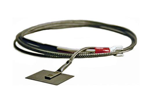
FIG. 1. A spade or butterfly-type thermocouple, placed between the nozzle body and heater band, can help maintain the setpoint temperature of the nozzle tip and body. Photo: Marathon Heater, Inc., marathonheater.com
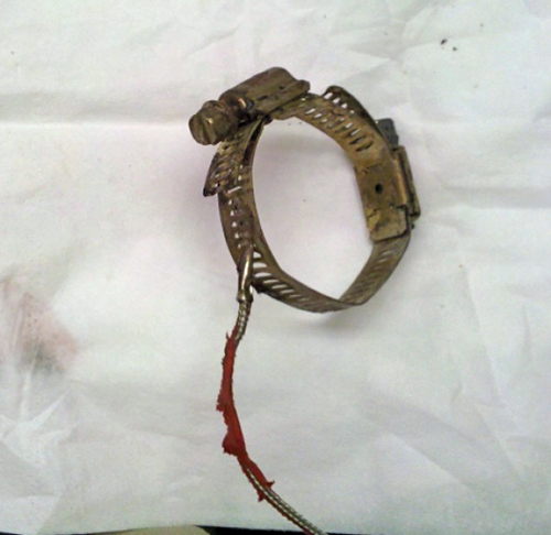
FIG. 2. A thermocouple situated on the heater-band clamp is unlikely to provide accurate temperature control of the nozzle tip and body. Typically, as shown here, there are gobs of plastic hanging from the wire, which is a safety hazard.


Most molders consider controlling the temperature of the nozzle tip and body a trivial detail. However, Dr. Deming tried to teach us about the importance of details, and ignoring this one will cost you money. Let’s start with some data, another foundation of Dr. Deming’s teachings that too many molders tend to ignore.
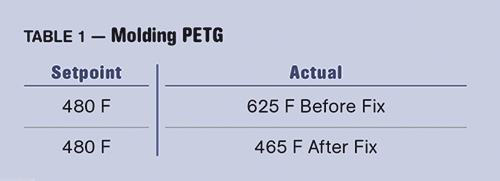
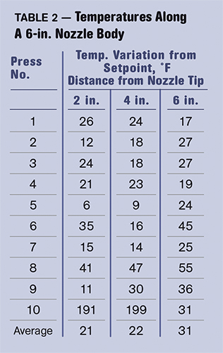
Table 1 shows a difference of over 150° F (65° C) between the setpoint and the actual measured temperature of the nozzle tip and body in a PETG molding operation. Reject rate was near 50%. Granted, this may not be typical, but in my experience it is not rare. And, yes, this was with a PID temperature controller, not just a Variac. Table 2 is more typical, in my experience. But both are unacceptable and need to be fixed for quality and consistent production. Why?


One of the primary variables in molding is using the resin within its proper temperature range, and just as important is that the melt be uniform in temperature. With temperature variations you will get rejects. Possible types of rejects include the following:
1. Blush,
2. Gloss differential,
3. Degradation,
4. Halos,
5. Color variation,
6. Texture variation,
7. Inconsistent properties,
8. Marbling,
9. Cold slug in the nozzle tip,
10. Drooling or Stringing,
11. Burn marks at the gate,
12. Asymmetrical filling,
13. Shot-to-shot variations,
14. Swirls.
Bottom line: This is a significant problem that costs molders tens of thousands of dollars a month, including hours of wasted time trying to adjust a perfectly good process. I do not have a complete fix, but the following will provide melt temperatures much closer to setpoint and significantly better consistency between machines.
First, perhaps to convince yourself you have a problem, take a walk through the production floor and check where the thermocouple is located on the nozzle body and/or tip on a number of machines. You will notice a lack of consistency. Sometimes the controlling thermocouple is on the heater band, others have it in the hex of a nozzle body. If the nozzle body is longer than 2 in., the hex is not the place to put it. Still others will have the thermocouple on the clamp around the heater band. You can bet money that one is not giving the temperature controller the right information. In fact, all of the above have significant problems.
Ideally, we would have a magical thermocouple that we’d put on the outside of the nozzle body and, through ultrasonic sound waves, microwaves, infrared, or some new technology, we would get an accurate temperature. Some might think the thermocouple must be in the melt, but that will not work. For a thermocouple to provide an accurate temperature, I am told it has to be at least six diameters into the melt. There is not enough room to do this. Further there are more high-pressure machines being used—with 25,000 to 40,000 psi plastic pressures—and I am concerned about the safety of a hole drilled in the nozzle.
To date, my best compromise is to first clean up the nozzle body. Get all of the charred plastic, etc. off until you have a clean steel surface. Obtain a spade, also known as a butterfly thermocouple (see Fig. 1). Place this directly on the nozzle body, using some thermal paste to help with heat transfer. Placement should be one-third the length of the nozzle body back from the nozzle tip. Put it on top and wrap it with three or four turns of glass tape. The heater band goes over the spade. The heater band should cover as much of the full length of the nozzle body as possible, and ensure that it is the right voltage, 110V or 240V.
Take another look at Table 1 to see the before and after results of this technique. Fig. 2 shows the molder’s setup before the fix, with a thermocouple on the heater-band clamp. Seriously, why do you buy a $50,000 to $250,000 piece of equipment and then put up with Neanderthal temperature-control technology? Also note that there is some plastic on the wire in Fig. 2. This is common, with globs of it hanging from the thermocouple and heater-band electrical wire. These wires should not be left to hang below the barrel; they should be routed on the side of the barrel out of harm’s way.


Related Content

How to Set Barrel Zone Temps in Injection Molding
Start by picking a target melt temperature, and double-check data sheets for the resin supplier’s recommendations. Now for the rest...
Read More
Melt Preparation Part 1: Melt Temperature Optimization
A homogenous melt is required for consistent part quality, but achieving it requires balancing a number of factors, including barrel usage and temperature as well as screw speed, backpressure and residence time. Learn how to prepare your melt for molding success in this two-part series.
Read More
How to Stop Flash
Flashing of a part can occur for several reasons—from variations in the process or material to tooling trouble.
Read More
How to Get Rid of Bubbles in Injection Molding
First find out if they are the result of trapped gas or a vacuum void. Then follow these steps to get rid of them.
Read MoreRead Next

Lead the Conversation, Change the Conversation
Coverage of single-use plastics can be both misleading and demoralizing. Here are 10 tips for changing the perception of the plastics industry at your company and in your community.
Read More
How Polymer Melts in Single-Screw Extruders
Understanding how polymer melts in a single-screw extruder could help you optimize your screw design to eliminate defect-causing solid polymer fragments.
Read More