
Five Steps Toward Better Plug Assists
With careful planning and adherence to best practices, crafting the right plug assist can put you on the path to high-quality, repeatable parts.

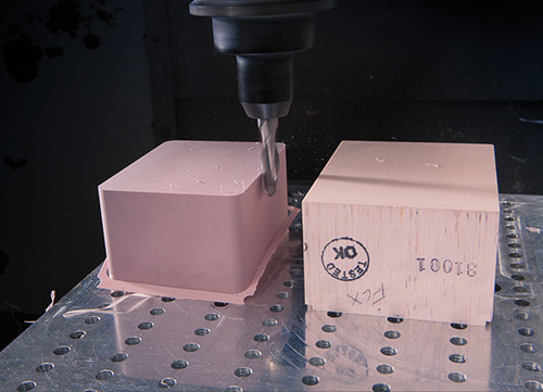
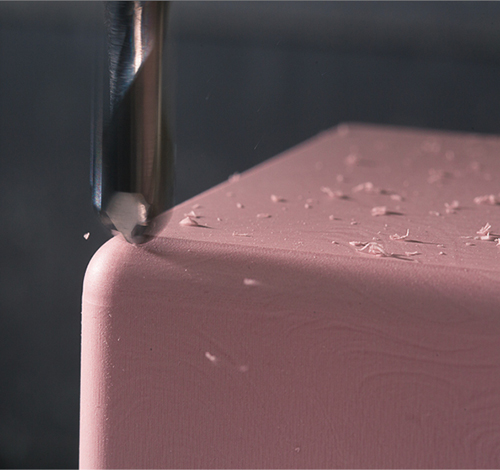
Solid carbide tools with high helix geometry designed to cut abrasive plastics produce the best results with optimal finish. Using the correct speeds and feeds will result in a better plug that produces repeatable thermoformed parts.
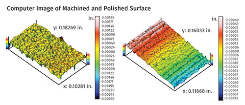
On a typical machined surface (left), the color changes represent height variation from peak to valley. This surface would feel smooth to the touch and could be used for most projects except those with high clarity requirements. On the right is a computer image showing a polished surface. The rounded peaks prevent scratching for high part clarity, yet the valleys still allow plastic to release from the plug.
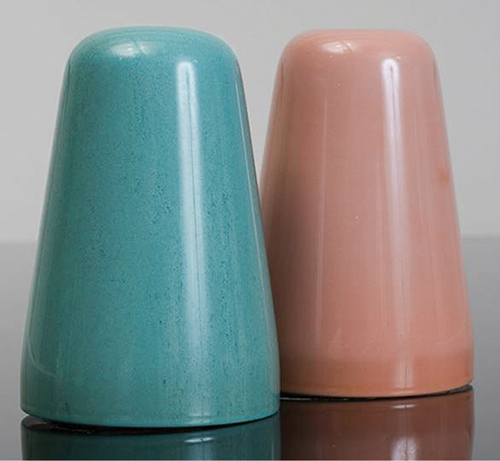
Above are examples of highly-polished copolymer (blue) and thermoplastic (mauve) syntactic foam plugs.


More than 90% of all thin-gauge thermoformed parts are formed with plug-assisted pre-stretching. While specific plug designs are dictated by many factors—including depth of draw, the number of mold cavities, the critical nature of the wall thickness, and the stretching characteristics of the plastic—certain fundamental techniques can help improve the repeatability of the forming process as it relates to the plug assist. This article outlines five practical steps that thin-gauge thermoformers and toolmakers should follow to optimize plug design and material selection.
The plug is an integral and critical component of a thermoforming project. It is the one element in the process that impacts the product shape, material distribution, clarity, and crush strength at the same time—all while the plastic is still in a transitional state. It is important to conduct a full comparison of the plug material costs and the trade-offs in material distribution, part weight, rejects, and other concerns, such as aesthetic quality. With careful planning and adherence to best practices, crafting the right plug assist can put you on the path to high-quality, repeatable parts.


Before examining the specific details of each step, it is important to point out that the user’s perspective plays an important role in this process. Depending on whether you are a thermoformer, toolmaker, or both, there are several elements to consider when choosing the right material. Simply put, some people have to design and build the plugs while others have to run the machines that are equipped with those plugs.
This is an important distinction when considering the thermoforming ecosystem, which includes suppliers and users of resin, extruders, converters, toolmakers, machine shops, OEMs, and other service suppliers. Changes in one part of the ecosystem affect decisions and outcomes in another. If a toolmaker simply selects one grade of material without understanding the interaction between the plug and the plastic, the processor might not be getting the best material for that project.
STEP 1: SELECT THE BEST MATERIAL
Not all plug materials are created equal. Solid polymers and syntactic foams are most commonly used in thin-gauge applications. (Wood is almost never used in today’s demanding environments.) For example, different grades of Hytac syntactic foam from CMT Materials are optimized for performance with different types of plastic, temperature, machining conditions, surface finish, durability, and price. It is not always advisable to simply use the same material as last time if other variables have changed. The processing parameters for multilayer films such as PE/EVOH/PE are certainly different than those for HIPS.
Making the right choice reduces machining costs, improves material distribution, enhances clarity, reduces plastic buildup on the plug, and maximizes plug life. These benefits accrue in different ways to different members of the ecosystem.
STEP 2: CONSIDER PLUG DESIGN & MATERIAL TOGETHER
Plug design is a complex issue involving many factors. Mold design, sheet choice, process temperature, thermoforming equipment, plug material choice, and more all play a role. The best practice is to begin with a “material safe” plug design. This means that the plug material should be as close to the cavity wall and floor as possible (commonly 1/16 in. or 1.5 mm) with a minimal radius at the nose of the plug. This allows for an increase in radius if too much material is carried to the base of the cavity. More plug taper can also be added to distribute material thickness evenly or to remove potential plug marks.
The intent of the plug is to pre-stretch and distribute plastic to the proper places. The initial interface point between the plug and the plastic will carry the greatest amounts of material. Sharp edges mean there will be less flow of plastic, resulting in thinner side walls and thicker base/corners. Round edges mean there will be more flow of plastic, resulting in thicker side walls and thinner base/corners. Different mold designs, machine features, plastic sheet characteristics, plug speed, vacuum venting/timing, and even operator techniques affect the performance of the plug.
It is important to recognize that different plug materials have different physical properties. This is seen most dramatically when designers are switching from nylon or acetal plugs to syntactic foam plugs. For example, since acetal has a higher coefficient of linear thermal expansion (CLTE) than Hytac syntactic foam, it must be designed to account for some expansion. If a designer is changing plug material without changing plug design, the material distribution of the final part will not be optimized and could lead to rejects and/or part failure.
In addition to CLTE, plug material strength (as measured by flexural toughness according to ASTM D790) can play an important role in design. It is important to choose a material that will meet thermoformed part strength requirements. For example, if the plug has narrow ribs or posts it is not a good idea to use a brittle material like some epoxy syntactics.
STEP 3: UNDERSTAND MACHINING GUIDELINES
Like many advances in material science, new tools are required for new materials. In the case of plug assists, traditional or legacy materials such as wood or commodity polymers are easily understood by CNC operators. Syntactic foam is a combination of hollow glass microspheres and thermoset or thermoplastic binder systems. The cutting mechanics are inherently different. Two key conditions must be met to get the best possible results: sharp cutting tools and adequate feed rates.
Cutting tools must be sharp to obtain a satisfactory surface finish when machining syntactic foam. Dull cutters or incorrect geometries will result in poor surface conditions. High-speed steel cutters are quickly dulled. Through research with tool manufacturers, CMT has found that solid carbide cutters with high-helix geometry are preferable for allowing a sharp edge and long tool life. Our trials revealed that a two-flute design worked best with abrasive syntactic foam.
To mill syntactic foam most effectively and to get the best possible surface finish, it is critical to understand the feed rate. The feed rate is a simple equation that includes chip load, spindle RPM, and the number of flutes on the cutting tool. Let’s look at each variable in turn. The chip load is typically provided by your tool vendor for a tool’s use with a specific type of material. The spindle RPM is generated by your machining center and the number of flutes is based on the actual cutting tool. Similar principles are applied to CNC lathes for turning cylindrical plugs, which are typically used for the production of drinking cups or yogurt containers.
The best guidelines are worthless if they are not communicated adequately to the right person. Often, the CNC operator and the tool designer are not working in tandem. This can result in miscommunication about tool-path design and actual CNC machine parameters. The same holds true when the tooling department is not fully aware of the needs of the processing department. The best results are achieved when the entire team understands the context of the project.
STEP 4: HOW & WHEN TO MODIFY THE PLUG SURFACE
There are different schools of thought on how to modify the plug surface. Most agree, however, that polishing the plug will result in a more repeatable process. Silicon carbide sandpaper is commonly used. When polishing thermosets and copolymer syntactic plugs, the sandpaper can be dipped in water. This helps reduce the build-up of dust in the grit. It should be noted that this method cannot be used for thermoplastic-based syntactics. Liquids will actually roughen the surface during the polishing process. Scuff pads and open mesh or micro-mesh sandpaper can also be used as they too reduce the amount of dust or build-up in the grit.
Temperature, substrate, surface finish, motion, dust, and many other factors affect the plug/sheet interface. Different surface conditions due to the machining or polishing of a plug material, or even a few degrees of temperature variation in a mold, will affect the coefficient of friction (CoF) and sheet stretch values. The value changes for each specific plastic relative to plug material and even from roll to roll of plastic. There is both a static (objects at rest) value and a kinetic (objects in motion) value for the frictional coefficient. The only suitable method for determining a CoF value is experimentation with the actual plug and sheet.
On the accompanying illustration, a computer image shows a typical machined surface on the left. The color changes represent height variation from peak to valley. This surface would feel smooth to the touch and could be used for most projects except those with high-clarity requirements.
On the right is a computer image showing a polished surface. Again, the color changes represent height variation from peak to valley. The rounded peaks prevent scratching for high part clarity yet the valleys still allow plastic to release from the plug. A properly polished plug will reduce scratching, optimize material stretch, increase plug life, reduce build-up, and improve the repeatability of the thermoforming process.
STEP 5: MOUNT THE PLUG SECURELY TO THE TOOL
The best plug design in the world won’t be worth much if it doesn’t function well in the heat of the thermoforming process. Fundamentally, the toolmaker wants to avoid creating undue stress in the plug, which could lead to breakage or failure. Some materials, such as thermoplastic-based syntactics, are extremely durable and can withstand direct threading. Other, more brittle materials require a different approach.
The geometry of the plug must also be considered. Inserts are an excellent way for maximum attachment. A bolt may be installed into a flush surface insert without flex of material or risk of plug damage. This method has the additional benefit of easier attachment/reattachment.


Related Content

How to Stop Flash
Flashing of a part can occur for several reasons—from variations in the process or material to tooling trouble.
Read More
Are Your Sprue or Parts Sticking? Here Are Some Solutions
When a sprue or part sticks, the result of trying to unstick it is often more scratches or undercuts, making the problem worse and the fix more costly. Here’s how to set up a proper procedure for this sticky wicket.
Read More
Tunnel Gates for Mold Designers, Part 1
Of all the gate types, tunnel gates are the most misunderstood. Here’s what you need to know to choose the best design for your application.
Read More
The Effects of Temperature
The polymers we work with follow the same principles as the body: the hotter the environment becomes, the less performance we can expect.
Read MoreRead Next
Why (and What) You Need to Dry
Other than polyolefins, almost every other polymer exhibits some level of polarity and therefore can absorb a certain amount of moisture from the atmosphere. Here’s a look at some of these materials, and what needs to be done to dry them.
Read More
Troubleshooting Screw and Barrel Wear in Extrusion
Extruder screws and barrels will wear over time. If you are seeing a reduction in specific rate and higher discharge temperatures, wear is the likely culprit.
Read More
Lead the Conversation, Change the Conversation
Coverage of single-use plastics can be both misleading and demoralizing. Here are 10 tips for changing the perception of the plastics industry at your company and in your community.
Read More