
Four Keys to Consistent Tubing
Troubleshooting Medical Tubing
Because of their use in critical applications, processors of medical tubing have little or no room for error.
Ensuring that the extruder is pumping as stably as possible is the first step to making consistent tubing. A control system that can graph the pressure readings is a very helpful tool for analyzing extrusion stability in a tubing system.
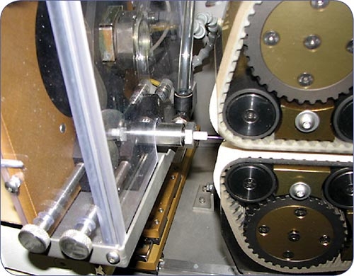
Venturi-type cutter bushings create a vacuum that draws the tube into them. Lubrication is still required to enhance feeding and wet the blade for optimized cut quality. Cut-length repeatability can also be enhanced by reducing this bushing drag.


Because of their use in critical applications, processors of medical tubing have little or no room for error. They confront many of same issues as other extrusion processors but cannot overlook even the smallest flaw. Typical problems that can impact tolerances and generate scrap in medical tubing are:
•Melt fracture,
•Pressure control,
•Gels,
•Downstream considerations.
Let’s review each of these problem spots in detail and see
how they can be resolved.


DEALING WITH MELT FRACTURE
Melt fracture is surface roughness (sharkskin appearance), a common issue when small tooling gaps are used with some polymers. Usually, the higher the viscosity of the polymer and the lower the melt temperature, the greater the probability of melt fracture.
Melt fracture is caused by a disruption of uniform flow along the metal surfaces when high shear is present. Typically, melt fracture occurs in the final tooling gaps and is a result of the shear rate on the polymer, which is a function of the tooling gap, melt viscosity, and output rate. Some of the resins that are most susceptible to melt fracture are HDPE, LLDPE, polycarbonate, fluoropolymers, and higher-viscosity thermoplastic urethanes.
High line speeds mean higher outputs, which increase the possibility of melt fracture. An obvious approach to minimizing melt fracture would be to slow down, which is usually the least favorable choice for the processor. Raising melt temperature may alleviate some of the surface issues, but that approach usually provides limited relief. Some dies have separate heaters for the final tooling, and increasing the temperature of that tooling usually has some positive effect.
The most logical approach to avoiding melt fracture is to utilize larger tooling gaps, which means making the tubing with a larger drawdown. This is done commonly with fluoropolymers, where melt fracture is quite evident. Tooling drawdowns of 2:1 or 4:1 are common for many polymers, whereas fluoropolymers have used drawdowns of 50:1 and larger. The larger the drawdown, the more difficult it becomes to hold tubing to the required size. Tooling land length does not offer much assistance in reducing melt fracture.
Some processes, like blown film, use special fluoropolymer additive masterbatches when extruding PE through small die gaps. The additive coats the metal surfaces and reduces or eliminates melt fracture. Medical tubing processors are limited by federal regulations in the kinds of additives they can use. If changing polymers is an option, a material with lower viscosity (higher melt index) should help reduce melt fracture.
Screw design does not offer much assistance for reducing melt fracture. A shallower screw might be used to increase the work on the material and thereby increase the melt temperature, but that only leads to a small improvement in melt fracture.
PRESSURE CONTROL STRATEGIES
Pumping consistency from the extruder is a key to holding good tubing tolerances. Getting the polymer to feed well early in the extruder, and having a screw design that controls the melting process, will lead to decent pumping stability at the end of the extruder and a good chance of small dimensional variation in the tubing.
The stability of an extruder can be measured by the pressure stability in the die adapter. If an extruder has issues getting a consistent feed (typical on extruders of 25-mm diam. or smaller), consider using a feed-section insert. It can be shaped with tangential geometry or grooves in the feed area. The screw must be designed to ensure stability all along its length. Even when the best attempts are made to control feeding and melting, some pressure variation is often seen on smaller extruders.
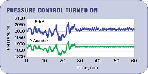
You can optimize your tolerances by adding a gear pump to your line. Or, as a less-expensive option, you can use a pressure-control setup that allows rapid control of screw speed to reduce variation measured in the die adapter. A control system that can graph the pressure readings is a very helpful tool for analyzing extrusion stability in a tubing system. An example of this type of control is shown in the graph opposite.
The left side of the graph (first 25 min of recorded runtime) shows pressure recordings from the transducer at the end of the screw (P-BP) and in the die adapter (P-Adapter). Screw flights going past the P-BP location (just before the breaker plate) cause the trace to show some variation at all times.
A high-speed recorder would define these pressure fluctuations as a “sawtooth” trace, occurring at the frequency of the screw rotation. The adapter pressure does not have the screw flight effect and shows a pressure variation on the left side of around 5%. Turning the pressure feedback controller on, and allowing screw speed to be rapidly trimmed, shows the pressure stability greatly improved. Tubing tolerances would also noticeably improve with this move. Small extruders react well to this feature, larger extruders not as well.
GELS—THE BANE OF TUBING EXTRUSION
Gels in extruded tubing are a problem as old as extruded tubing itself. Gels are seen as bumps on the tubing surface. Their size depends on the source. The thinner the tubing wall, the more obvious the gels typically become. Some of the polymers that seem to be gel-prone are flexible PVC, TPU, and some other TPEs.
Gels can come from a number of sources, including material inconsistencies, degradation, crosslinked particles, and contamination. Gels in flexible PVC are typically the result of PVC resin particles that have not absorbed enough plasticizer, causing them to “float” along with the melt. They are typically impossible to break down along the screw, and are also difficult to trap in screen packs or filters. If a particle can pass through a screen of 250 to 300 mesh, there is no way a screw would have any chance of breaking it down. There are some claims of single-screw extruders removing these gels, but a trial should be run to prove the point.
Thermoplastic urethanes can have issues with durometer differences throughout the extrudate, especially where the material has been made from different durometer stocks. The resulting viscosity differences can be reduced via shear mixing along the screw. The mixing level would need to be tested on a given screw to see if acceptable tubing can be obtained for a given output rate.
Gels should be investigated to try to discover their source and how they can be minimized. Attempting to melt them can sometimes be done on a heated, temperature-controlled surface, to determine their melting point versus that of the bulk of the material. The gels may not melt at all, which indicates the severity of the problem. Another clue is whether the gels are a different color from the main material, suggesting degradation or contamination.
To solve the problem, first try a high-shear screw with elevated barrel temperature settings to see if the gel level can be reduced by shear and temperature. If the gels are not reduced noticeably—unfortunately the usual case—you can assume the screw won’t solve the problem.
The options then are to either find a way to filter out the gels with a fine-mesh and large-area filter, or have the gels removed prior to extrusion. Obtaining lower-gel polymers is difficult in most cases, since material suppliers are often not motivated to make the extra effort for the relatively small volumes used by medical tubing processors.
Some medical tubing processors have taken the time and expense to repelletize the materials to provide an additional heat history to help melt or break down the gels and permit an additional filtering step. Filtering must be fairly fine (40-50 microns or finer) to have a noticeable effect and should have a large filtration area to allow adequate run time before a buildup of gels on the filter results in unacceptably high pressure. Canister filters or large-area breaker plates (with sintered metal filters) are commonly seen in these high-filtration situations.
DOWNSTREAM ISSUES
When attempting to optimize the cutting and feeding of medical tubing, cutter bushings are often overlooked, though in many cases they are as important as, or even more important than, the blade itself. Many medical tubes are both small and low in durometer, factors which make them difficult to feed to the cutting blade.
PTFE inserts can help to reduce drag in the bushings, but often require an FDA-approved lubricant (such as alcohol or distilled water) either dripped or sprayed on the tube as it enters the bushing to further decrease drag.
So-called venturi (air-feed) upstream bushings are also becoming more common. These create a vacuum that draws the tube into the bushings. In most cases, even with air-feed bushings, lubrication is still required to enhance feeding and wet the blade for optimized cut quality. Cut-length repeatability can also be enhanced by reducing this bushing drag.
Sharp edges should be maintained on the cutting surfaces of both the upstream and downstream bushings, with the downstream cutter-bushing bore typically 0.003 to 0.005-in. larger than the upstream bore to offset any potential misalignment. Never chamfer the exit cutter bushing, as this leads to burrs on the cut site.
The bushing surfaces should be maintained on a regular basis, ground and polished so as not to scratch the surface of the blade, which in turn can cause scratches on the tube cut site. And be sure the razor blade has no burrs on the back edge, as these, too, can cause scratches on the tube cut surface.
The gap between the cutter bushing should be no more than 0.001 to 0.002 in. larger than the thickness of the cutting blade. Excessive gap leads to burrs on the cut tubes. Blade choice is also very important. Blades that are too thick for the particular cutting application can leave burrs on the cut tubes. New blades are now available down to 0.004-in. thick, with optimized shapes to offer the best cutting angles and low product interruption.
It is important that blades be held in close proximity to the actual cut site to offer optimum blade support while using the thinnest blade possible. In all cases, the blade should be lubricated to minimize heat generation and creation of particulates (hairs, fuzz).
Simple blade wipes, misting systems, or reservoir troughs are used with great success.


Related Content

Specialty Purging Compounds Optimize Color and Material Changeovers
Selecting of the correct purging compound can speed up material and color changeover time and reduce scrap. You’ll even save on material.
Read More
Understanding Melting in Single-Screw Extruders
You can better visualize the melting process by “flipping” the observation point so that the barrel appears to be turning clockwise around a stationary screw.
Read More
Cooling the Feed Throat and Screw: How Much Water Do You Need?
It’s one of the biggest quandaries in extrusion, as there is little or nothing published to give operators some guidance. So let’s try to shed some light on this trial-and-error process.
Read More
Avoid Four Common Traps In Granulation
Today, more than ever, granulation is an important step in the total production process. Our expert explains a few of the many common traps to avoid when thinking about granulators
Read MoreRead Next

Medical Tubing: Tinier Than Ever And Much More Complex
Medical tubes are becoming ever smaller and thinner while adding new features like high-tech material combinations, more wire braiding/wrapping, and heat-shrink sheathing for strength and kink resistance.
Read More
How Polymer Melts in Single-Screw Extruders
Understanding how polymer melts in a single-screw extruder could help you optimize your screw design to eliminate defect-causing solid polymer fragments.
Read More
Understanding Melting in Single-Screw Extruders
You can better visualize the melting process by “flipping” the observation point so that the barrel appears to be turning clockwise around a stationary screw.
Read More