
How to Fix Pinch-Off Failures
Extrusion blow molded parts often fail at the parison pinch-off seam of the mold parting line.


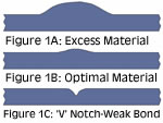
Fig.1-Forming the correct material shape inside the pinch-off is critical to part performance. That shape is determined by both the pinch-off design and processing conditions.
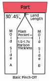
Fig.2A-Changing the amount of material compression in the flash pocket will also change the amount of material on the inside of the part at the pinch-off seam.
Fig.2B-In case of excess material inside the part at the seam, adding half-round channels to the flash pocket provides more volume and less compression of flash material so less is forced back into the part.
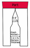
Fig.2C-If the problem is too little material inside the pinch-off, one solution is this step-down design of the flash pocket to press more material back into the part.
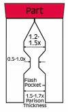
Fig.2D-Two opposed dams to compress material into the part will solve problems of thinning at the pinch-off.
Extrusion blow molded parts often fail at the parison pinch-off seam of the mold parting line. Common forms of part failure at the pinch-off are cracking from impact, fatigue failure from flexing, or chemical stress cracking. Once the mode of failure is identified, the appropriate processing changes or pinch-off design modifications can be selected to optimize part performance and appearance.
Part failure along the parting line is related to material processing conditions, parison geometry, molding conditions, mold design, or a combination of these factors. Developing the optimal material shape inside the part at the pinch-off is a key to building parting-line integrity.


The pinch-off mold section is designed to cut through the excess extruded material (flash) that extends beyond the part and separate it along the mold parting line. When the mold closes on an extruded parison, three segments are formed: the top flash (parison between the die and the part), the part, and the bottom flash/tail (parison below the part). In some cases, the whole part is surrounded by flash and is considered fully flashed (part plus flash).
The array of pinch-off designs is endless, often selected from experience or designed for use in specific applications. For instance, multilayer barrier pinch-offs require bonding or manipulation of the barrier layer to maintain the part’s barrier properties. Some mold designs, including pinch-off designs, are patented, so it is always best to check before redesigning.
Optimizing the seam
Both processing conditions and mold pinch-off geometry will influence the shape of the material inside the part and the integrity of the parison bond. The objective is to produce a consistent material geometry along the pinch-off weld. Figure 1 illustrates common shapes of the material inside the part at the pinch-off. Figure 1A shows excess material along the seam. That excess material is likely to shrink and warp because it is not cooled at the same rate as the surrounding part wall. Slower cooling may also increase the residual stress and degree of crystallinity in some materials such as HDPE, increasing the tendency for chemical stress cracking.
Figure 1B shows a seam configuration optimal for cooling and strength. The material thickness is the same as or slightly thicker than the adjacent part wall.
Figure 1C illustrates a “V” notch or weak bond area. This seam is likely to split with impact or show fatigue failure with bending. Some materials, like polycarbonate, tend to have impact failure with both thin notched sections and thick stiff sections.
To evaluate and correct part pinch-off failures, first confirm that the part weight and material thickness are within specifications. Second, cut the part and examine the parting-line pinch-off and wall thickness throughout the part. Under magnification, examine the outside of the part along the pinch-off for a notch or indentation, which can occur from flash that is removed too hot or too cold or from damage to the mold pinch-off land. Check the land for “coining” damage if a notch is found.
Process adjustments should be tried to improve material distribution and bonding before considering making changes to the mold. Consider the following types of process changes for pinch-off improvement:
- Material compression in the flash pocket: Changing parison thickness and the mold slow-close speed and cushion will change the amount of material squeezed back into the part. Adjust the slow-close distance and cushion just before mold lock-up to add or decrease material pushed back (Fig. 1). Also, the parison melt viscosity varies according to the melt temperature and material type. Higher-viscosity material causes greater material push-back into the part.
- Material delivery: Confirm that the parison melt temperature and moisture levels are within the manufacturer’s recommended conditions. Adjust parison programming to distribute the material uniformly as per product specifications. Change die and/or mandrel size to adjust parison diameter and wall thickness. Add parison die shaping to distribute material more evenly in the part.
- Mold location and movement: Close the mold at a speed that captures the parison uniformly, minimizing material sag and allowing the air to vent. Also, adjust the mold location in relationship to the die and any pre-pinch device.
- Air management: Adjust the pre-blow and blowing air pressures and flow rates. A pre-pinch device can be added or adjusted to help capture air in the parison and improve material distribution without a blowout. Also, adjust blowing air duration and pressure to optimize part cooling. Examine the part’s outer surface to confirm that mold venting is adequate.
To properly evaluate your efforts to improve the pinch-off seam, be sure to document all processing and mechanical changes in the sequence that they were made. If possible, keep digital pictures of the results of changes for the record.
Fixing pinch-off design
If processing changes do not correct pinch-off failures, it’s time to look at pinch-off design geometry. Compare the material geometry formed inside the part by the pinch-off with those in Fig. 1. In some cases, the design for optimal pinch-off material uniformity will change in different sections of the mold, i.e., top versus bottom. A new mold is usually built “metal-safe” so that mold changes can be made by removing metal. Consider several approaches to design changes before committing to mold modification. Also confirm the location of mold cooling lines and internal components and ask the mold maker for suggestions before making any mold modifications.
Excess material inside the part at the pinch-off, like in Fig.1A, is reduced by decreasing the material compression in the flash pocket. The solution in Fig. 2A is a relatively simple mold modification to increase the flash pocket depth. The solution in Fig. 2B consists of half-round channels that are added perpendicular to the pinch-off to reduce the amount of material that is compressed close to the pinch-off land. The compression area adjacent to the pinch-off land is maintained to provide better response to changes in molding conditions. Modification 2B also shapes the flash to improve cooling and make the flash more rigid and less likely to fall back on the part. The 2B design is also less sensitive to minor fluctuations in parison thickness and length.
Thin material inside the part at the pinch-off (Fig. 1C) is alleviated by forcing additional material back into the part by increasing the parison compression or by restricting material from moving away from the pinch-off. A simple way to increase compression in the flash pocket is by adding metal on each mold half to decrease the flash pocket depth. A flash pocket depth of 1.4 to 1.7 times the parison wall thickness will usually create sufficient material compression in the flash pocket. Figure 2C adds a step-down flash pocket and Fig. 2D uses two opposed dams to compress material into the part.
Depending on the mold material and configuration, dams may be added to the flash pocket without changing the entire flash pocket surface area. Dam height and width can be modified if further changes are required. Always confirm that clamp tonnage is adequate for the increased material compression area while maintaining adequate blowing-air pressure.
A key component of the pinch-off is the land, a short parallel section that helps bond the material and separates the part from the flash. The land length is usually 0.125 to 0.380 mm (0.005 to 0.015 in). A longer land is more durable and produces more separation of the part and flash for improved cooling and trimming. A short land and small gap are more susceptible to damage or coining. Metal in the land should be hardened or made of a harder metal if wear from the plastic or fillers is an issue.
The land gap or separation is controlled by the mold lock-up position and by the distance the land is cut below the plane of the mold parting surface. Land thickness can be adjusted to create optimal flash thickness for easy part removal and trimming. With thin material in the land, the flash may fall off the part during the mold opening, before the part is removed. The land can be deepened if the flash separates from the part too easily. Thicker flash is stiffer, which aids part handling and flash removal. A thick land gap is often used with larger parts to aid part removal and handling, but it makes parts more difficult to trim for good appearance.
Also, changing the angle of the land to the flash pocket influences the material push-back. A sharper angle will cut through the parison with less material push-back.
Lewis Ferguson has 40 years of experience in the plastics industry, much of it in blow molding PVC and engineering thermoplastics. He worked in material and process development at Tenneco Chemical, Borg-Warner Chemicals, and GE Plastics. After retiring from GE in 1998, he founded Parisons, a blow molding consulting business in Stone Harbor, N.J. He can be reached at (609) 368-7230 or by e-mail at parisons@aol.com.


Related Content

Get Color Changes Right In Extrusion Blow Molding
Follow these best practices to minimize loss of time, material and labor during color changes in molding containers from bottles to jerrycans. The authors explore what this means for each step of the process, from raw-material infeed to handling and reprocessing tails and trim.
Read More
How to Extrusion Blow Mold PHA/PLA Blends
You need to pay attention to the inherent characteristics of biopolymers PHA/PLA materials when setting process parameters to realize better and more consistent outcomes.
Read More
How Was K 2022 for Blow Molding?
Over a dozen companies emphasized sustainability with use of foam and recycle, lightweighting and energy savings, along with new capabilities in controls, automation and quick changeovers.
Read More
Understanding the ‘Science’ of Color
And as with all sciences, there are fundamentals that must be considered to do color right. Here’s a helpful start.
Read MoreRead Next

Advanced Recycling: Beyond Pyrolysis
Consumer-product brand owners increasingly see advanced chemical recycling as a necessary complement to mechanical recycling if they are to meet ambitious goals for a circular economy in the next decade. Dozens of technology providers are developing new technologies to overcome the limitations of existing pyrolysis methods and to commercialize various alternative approaches to chemical recycling of plastics.
Read More
How Polymer Melts in Single-Screw Extruders
Understanding how polymer melts in a single-screw extruder could help you optimize your screw design to eliminate defect-causing solid polymer fragments.
Read More