
How to Injection Mold Cyclic Olefin Copolymers
This new family of clear engineering thermoplastics made its first big splash in extrusion, but now injection molders are learning how to process these amorphous resins into optical and medical parts.


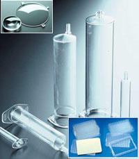
A lot has been learned in the last few years about how to injection mold COC materials for best results in sensitive medical and optical applications. Micro-vial holders, syringe bodies, and lenses are just now making a commercial impact
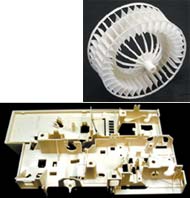
Development of new filled, reinforced, flame-retardant, and impact-modified COC grades will open up applications like this business-machine deck (above) and automotive air-conditioning fan (top).
Ticona's Topas COCs exhibit good flow, filling complex molds and thin walls easily
This new family of clear engineering thermoplastics made its first big splash in extrusion, but now injection molders are learning how to process these amorphous resins into optical and medical parts.
The first substantial wave of molded applications for the Topas family of metallocene-catalyzed cyclic olefin copolymers (COCs) is just now arriving on the market. Some limited molding activity with these new transparent engineering thermoplastics dates back to 1969, but injection molded (and injection-blow molded) medical and optical applications are only now starting to appear in force. Emerging uses include optical lenses, light guides, microtiter plates, syringe bodies, tubing connectors, catheter manifolds, and lids.


Ticona introduced Topas COCs five years ago as a lower-cost alternative to other COC materials produced by non-metallocene technologies. The first commercial plant (66 million lb/yr) started up in 2000. Metallocene-catalyzed COCs offer excellent optical properties, high flow, and ultra-low moisture absorption. In addition, their density is 3% lower than that of polystyrene and 15% less than polycarbonate and acrylics.
(2021 Update: Topas COC was developed in the 1990s by Hoechst Celanese, and initially marketed by Ticona. After a couple of reorganizations and ownership changes, Topas COC is today manufactured by Topas Advanced Polymers GmbH, a company of the Polyplastics Group, and outside EMEA is sold by Polyplastics. The company will soon be adding a second plant for the manufacture of COC, thanks to growing global demand in medical and packaging applications.)
Up to now, these properties have been exploited mainly in extruded film and sheet. For injection molders, COCs offer glass-like transparency and excellent barrier to water vapor with high HDT and good electrical properties. COCs are amorphous polymers with high modulus and surface hardness. Chemically, they resist hydrolytic degradation, aqueous acids and bases, and most polar and oxygenated solvents. In injection molding, they provide high precision, and they flow well to fill complex, thin-walled parts with low shrinkage and warpage. Because COCs’ stiffness is 25% greater than that of polycarbonate, they lend themselves to molding thinner walls.
COC properties & molding
Injection molding grades of COC from Ticona have a glass-transition temperature (Tg) between 70 and 185 C (158 to 365 F). As a result, their heat-deflection temperature (HDT) ranges from 75 to 170 C (167 to 338 F). Grades with Tg above about 140 C (284 F) have a flexural modulus in the vicinity of 500,000 psi and elongation at break of 3% to 4%. Those with a lower Tg have a lower modulus but greater elongation (up to 10%).
Post-molding shrinkage of COCs typically falls between 0.4% and 0.7%. Shrinkage is greater with higher Tg grades and tends toward lower values as cavity pressure rises. Shrinkage in the flow direction is only slightly greater than that in the transverse direction, so very flat parts can be molded. COCs’ good stiffness and flow means that parts can have walls down to 1 mm or less.
The resin replicates extremely fine mold features. One precision COC laboratory component, for instance, has complex channels as small as 10 microns. COCs also faithfully reproduce sub-micron surface patterns, such as those found on diffraction gratings and optical data-storage media.
Only neat grades of Topas COC have been offered until now, but glass-reinforced, mineral-filled, flame-retardant (UL 94V-2 and V-0), and impact-modified grades have been developed. Ticona has also made grades containing stainless-steel fibers to impart electrical conductivity. These new modified grades will open up potential in business machines, communications equipment, and automotive parts like headlight reflectors and air-conditioning fans.
Equipment considerations
COCs are usually molded on conventional machines having general-purpose, low-compression screws with ratios of 2.2:1 to 2.5:1. Screws are typically shallow single-flighted or barrier models made from standard tool steels. The screw should homogenize the melt gently because excessive shear heating can cause yellowing and optical inhomogeneity. A high-compression screw can generate too much shear and even shatter the pellets.
Optical parts are best processed in machines with higher screw L/D ratios, which tend to produce less splay and improve recovery times with lubricated grades. Barrels do not need venting because of the resin’s negligible water absorption.
COCs can be used with all types of nozzles, although free-flow, open types are best because they allow for easier sprue pullout. The resin also can be used with nearly all gating styles. Fan gates are recommended because of their relatively low shear. Gate size should be generous enough to prevent excessive shear heating or premature freeze-off. Gating preferably should be into the thick end of a part and gate diameter should be at least 60% of the wall thickness.
COCs with Tg above about 280 F should be run on oil-heated tooling. Grades with a lower Tg can use a circulating hot-water system for mold-temperature control.
| Injection Molding Topas COCs (Typical Start-up Conditions) | |||||
| Grade | 8007 | 5013 | 6013 | 6015 | 6017 |
| Cylinder Temp., F Feed Rear Center Front Nozzle |
<140 374-428 392-464 428-482 428-482 |
<230 410-464 446-509 446-509 446-482 |
<230 446-482 464-518 464-518 446-500 |
<230 464-518 482-554 482-554 464-500 |
<230 464-518 482-572 482-572 464-536 |
| Melt Temp., F | 374-482 | 464-518 | 464-518 | 500-572 | 500-572 |
| Mold Temp., F | 104-158 | 230-266 | 230-266 | 230-300 |
266-338 |
Tools can be made of standard mold steels but should be polished well to eliminate surface imperfections. This is vital for optical applications, where a finish down to a quarter of a wavelength of light may be required.
Because of COC’s low shrinkage, draft angles should be as large as possible—especially for parts with longer bearing lengths—to avoid distortion and demolding difficulties. Sticking can be a problem on parts with a shallow draft. Draft usually falls between 2° and 5°, though draft as low as 0.5° has been used successfully in some cases.
Draft is affected by part length and must be higher with textured surfaces. Molders switching to COC from a material with greater shrinkage should modify the tool so it has sufficient draft for part release. If the tool was previously used for polycarbonate or acrylic, it can typically run COC without any modification.
|
Machine Settings for Injection Molding COC
|
|
|
Injection Pressure, psi
|
7000-16,000
|
|
Hold Pressure, psi
|
6000-10,000
|
|
Injection Speed
|
Moderate to Fast
(0.5 to 6 in./sec) |
|
Backpressure, psi
|
>50 for GP molding
>100 for improved optics |
|
Screw rpm
|
50-200
|
|
Screw Suck-Back
|
None
|
|
Cushion
|
Small (4 mm typical)
|
|
Screw Type preferred
|
Low compression
|
|
Nozzle Type
|
Free-flow
|
|
Drying
|
Not normally needed
|
Molding guidelines
COCs absorb almost no water and do not need drying. If the resin does become wet, surface water can be driven off by about 2 hr of heating at 54° F below the resin’s HDT.
When feeding COC pellets, allow them to warm up in the feed throat to 45° to 54° below the HDT by throttling back on the cooling water. This makes the pellets less brittle and therefore less likely to generate fines that can affect part homogeneity.
Screw speed is usually in the moderate-to-fast range (50 to 150 rpm), depending on screw diameter and barrel size. The smaller the screw, the higher the rpm needed. Take care to homogenize the melt well, but without undue shear heating.
Cylinder temperatures should be matched to the Tg of the grade used (see table). Melt temperatures are typically 200° to 215° F above the Tg and usually fall between 464 F and 572 F. (Molders tend to run at the high end of this range.)
So far, COCs have been molded almost exclusively on reciprocating-screw injection presses. Though there is little industry experience with COCs in two-stage screw/ plunger systems, their thermal stability should be adequate for use in such a system.
Mold temperature for COCs should not be more than 90° F below the Tg for lower-temperature grades and not more than 54° below Tg for high-heat grades. Warmer molds minimize silver streaks, decrease molded-in stresses, and preserve clarity. Because COCs set up rapidly and their viscosity rises steeply as they cool towards Tg, molds should be hot enough to minimize weld-line formation.
Injection moldable COCs have melt flow rates between 1 and 56 g/10 min at 260 C. Shot size should be one-quarter to one-half the capacity of the barrel. COCs can withstand barrel residence time of about 15 min at normal molding temperatures. If process interruptions are likely to be longer, maximum barrel temperature should be reduced to 302 F to avoid yellowing.
Normal fill times are about 1 to 2 sec and cycle times typically extend from 10 sec for small, thin parts to 360 sec for parts 0.5-in. to 1-in. thick. Fill times for optical parts may be extended to 5 or 10 sec when using a mold temperature within 50° F of Tg.
Residual stress in parts can be limited by increasing injection speed in steps and by using mold temperatures as close to the resin’s Tg as possible. For low-stress parts, you should also avoid overpacking and long hold times. Try reducing holding pressure in stages to between 4000 and 7000 psi.
Given COCs’ low shrinkage, lubricated grades and mold-release agents can help in removing parts from a mold, especially if long cores are present. Choose mold sprays carefully to ensure they do not leave part surfaces hazy. Mold release can be helped by maintaining holding pressure a bit longer so the part relaxes before it is extracted.
COC parts emerge from the mold with smooth surfaces and need little or no deflashing or finishing. They have a soft surface until they cool completely, so just-molded parts should be handled carefully. If possible, degate COC parts when they are still warm. For degating cold parts, use a band saw because snipping can cause fractures.
COCs retain mechanical properties well over multiple regrind cycles and as much as 20% regrind can be used in many parts. Reground COC may yellow slightly during molding, so regrind cannot be used in optical applications or where very high clarity is needed.
When molding optical parts, use a high mold temperature and keep injection speed as fast as possible to prevent flow marks. On the other hand, slower injection may be needed to overcome sinks, voids, and birefringence in thick optical parts. Some suck-back may be needed to prevent nozzle drool. Higher backpressure—as much as half of a machine’s maximum pressure—helps improve optical properties but should not be so high as to yellow the part or hinder screw retraction. Low holding times and pressures are also usually good for optical parts. Holding time varies from 30 to 60 sec, depending on part thickness. Cooling time can last from 60 to 120 sec. Longer cooling time helps reduce stress level in the part. Total cycle time for optical parts is typically 2 to 5 min.
COCs should be processed in hot molds to maximize flow length and weld-line strength and prevent shock freezing that can embrittle parts and make them prone to stress cracking. Hot molds also reduce haze, splay marks, and streaks and improve surface quality.
Mold temperature is often the determining factor in reducing haze in optical parts. Each COC grade has an optimum mold temperature that minimizes part haze. Streaking can be controlled by using the proper balance between injection speed and mold temperature. Bubble formation and nozzle drool can be reduced by using moderate backpressure (between 20% and 30% of maximum). If discoloration occurs in parts that need extreme clarity, it helps to use a nitrogen blanket over the hopper to keep oxygen away from the resin.contaminants in COCs can cause bubbling, black specks, haze, and smoky swirls in clear parts. To prevent this, molders should thoroughly purge other materials from the barrel and feed areas and from material-transfer systems. It is best to remove the screw and clean both it and the barrel.
Secondary operations
COCs can be finished by printing, coating, and metalizing as well as joining and machining. COCs are nonpolar materials, so relatively few materials stick to them. Before a COC part can be printed or coated, it needs corona or plasma pretreatment to functionalize its surface and allow bonds to form. Metal coatings are an exception: Vacuum-deposited aluminum, chromium, silver, nickel, and other metals adhere well to COCs without pretreatment.
COC parts can be solvent bonded using a 15% solution of COC in cyclohexane, heptane, or other aliphatic solvent. Some commercial adhesives, such as those based on polyurethane, also work well with this polymer.
COCs can be ultrasonically welded to depths of 0.5 to 1.0 mm in 1 to 3 sec. Vibration amplitudes are typically 15 to 35 microns.
In machining COC parts by cutting, drilling, and diamond turning, cuts should be conservative and made at relatively low speeds. This keeps the applied force low, so the COC does not shatter, and it prevents excessive heat build-up. Common machine oils attack COCs and can cause cracking, so coolants must be water-based and machine surfaces and tools must be free of oil.
A lot has been learned in the last few years about how to injection mold COC materials for best results in sensitive medical and optical applications. Micro-vial holders, syringe bodies, and lenses are just now making a commercial impact.


Related Content

New Entrant Heartland Polymers Stepping up as Reliable Supplier
Heartland Polymers’ new Alberta, Canada facility will produce 525 KTA propylene and 525 KTA polypropylene. It is expected to stabilize supply chains across the continent.
Read More
The Effects of Stress on Polymers
Previously we have discussed the effects of temperature and time on the long-term behavior of polymers. Now let's take a look at stress.
Read More
The Importance of Melt & Mold Temperature
Molders should realize how significantly process conditions can influence the final properties of the part.
Read More
How to Optimize Injection Molding of PHA and PHA/PLA Blends
Here are processing guidelines aimed at both getting the PHA resin into the process without degrading it, and reducing residence time at melt temperatures.
Read MoreRead Next

Troubleshooting Screw and Barrel Wear in Extrusion
Extruder screws and barrels will wear over time. If you are seeing a reduction in specific rate and higher discharge temperatures, wear is the likely culprit.
Read More
Processor Turns to AI to Help Keep Machines Humming
At captive processor McConkey, a new generation of artificial intelligence models, highlighted by ChatGPT, is helping it wade through the shortage of skilled labor and keep its production lines churning out good parts.
Read More
People 4.0 – How to Get Buy-In from Your Staff for Industry 4.0 Systems
Implementing a production monitoring system as the foundation of a ‘smart factory’ is about integrating people with new technology as much as it is about integrating machines and computers. Here are tips from a company that has gone through the process.
Read More