
How to Solve Common Ultrasonic Welding Problems
Understand and address the likely origins of welding problems to keep production on track.


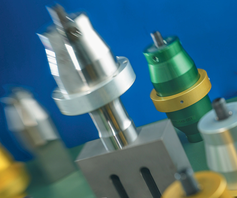
High-frequency vibrations are applied to two parts’ surfaces by a vibrating tool, commonly called a “horn” or “sonotrode.”
Ultrasonic welding is a widely recognized and accepted process for joining thermoplastic materials. It offers many advantages, including process reliability and repeatability, lower energy usage than other joining techniques, material savings (because there is no need for consumables, such as glue or mechanical fasteners), and labor savings.
But as with any process, there are situations where apparent problems with this technique may interrupt the production process. The key to resolving and avoiding these problems is to understand their likely origins. Processors that are successful in using ultrasonic welding typically share two principal traits: they have a well-documented, validated welding process; and that process is supported and maintained by a resident well-trained “champion.” If one or both of these important factors are not present, you’ll likely very soon call for help. Even with both present, it is possible that you’ll need some help or technical assistance at least once in a while.


Related Reading: A Guide to Ultrasonic Welding Controls
How the Ultrasonic Welding Process Works
Before examining common causes of ultrasonic welding problems, let’s take a moment to understand the welding cycle itself. In ultrasonic welding, high-frequency vibrations are applied the surfaces of two parts by a vibrating tool, commonly called a “horn” or “sonotrode.” Welding occurs as the result of frictional heat generated at the interface between the parts. The ultrasonic vibrations are created by a series of components—the power supply, converter, booster, and horn—that deliver mechanical vibration to the parts.
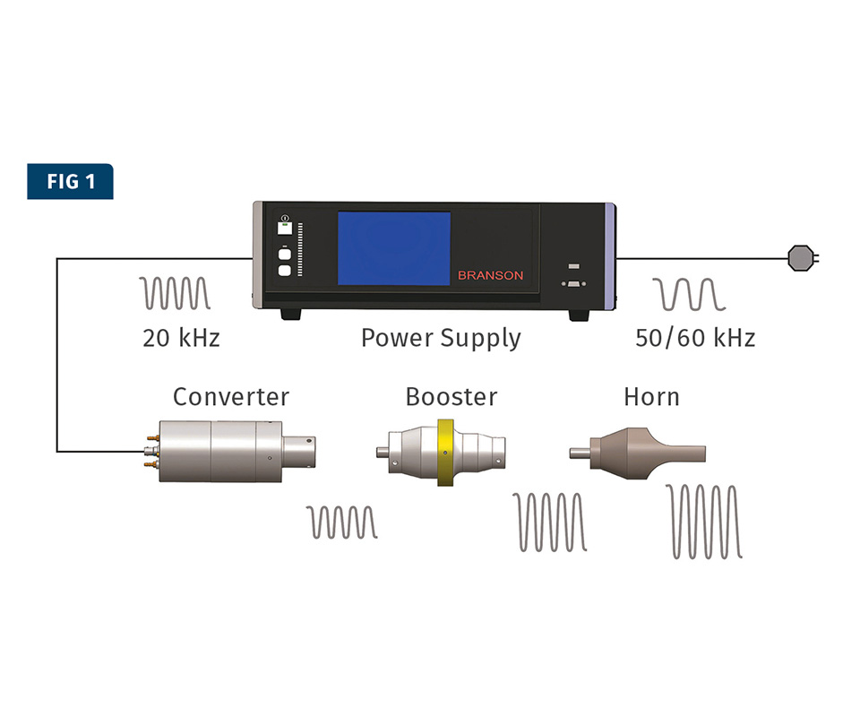
The power supply takes a standard electrical line voltage and converts it to an operating frequency.
As shown in Fig. 1, the power supply takes a standard electrical line voltage and converts it to an operating frequency. In the following example, we will utilize a common ultrasonic welding frequency of 20 kHz, though welding can take place over a range of 15 to 60 kHz to meet specialized needs. In operation, the power supply sends electrical energy at the specified frequency through an RF cable to the converter. The converter utilizes piezoelectric ceramics to convert the electrical energy to mechanical vibrations at the operating frequency of the power supply. This mechanical vibration is either increased or decreased based on the configuration of the booster and horn. The proper mechanical vibration amplitude is determined by an applications engineer and is based on the thermoplastic materials used in the parts.
Higher-frequency welders are considered “more gentle” in the application of ultrasonic energy to parts.
The parts to be welded are put under a mechanical load, generally with a pneumatic actuator that holds the booster and horn. Under this load, the mechanical vibrations are transmitted to the interface between the material surfaces, which focuses the vibrations to create intermolecular and surface friction. This friction creates heat and a subsequent melt, which solidifies into a welded bond.
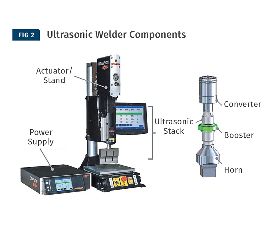
Basic components of an ultrasonic welder.
The basic components of an ultrasonic system are a power supply, an actuator, and a stack (see Fig. 2). The power supply takes line voltage at a nominal 120-240V and transforms it into a high-voltage, high-frequency signal. It also contains the programming necessary to operate the actuator and stack in a controlled manner to achieve a desired weld result. The actuator, either pneumatically or electric servo-operated, and available as a stand-alone benchtop unit or integrated into an automated system, moves the ultrasonic tooling toward the parts to be joined. It applies the needed force to the materials to help create the welding conditions.
The ultrasonic stack completes the system. It transfers vibratory energy, through direct contact with the parts, to the sealing/joining surface. The stack typically consists of three items: the transducer or converter (described above), which contains the piezoelectric ceramic crystals that oscillate at the frequency of the applied power-supply signal. As these crystals oscillate, they physically expand and contract, creating measurable mechanical motion (referred to as peak-to-peak amplitude) in the output side of the transducer.
The second section, the booster, with an attached ring in its mid-section, serves two functions: It acts as a mounting point for the stack into the actuator, and also serves to amplify or reduce the output motion created in the transducer.
Heeding “a squeaky wheel” sooner rather than later may well permit identification and resolution of a problem before production is adversely affected.
The third and final component of the stack is the horn (sonotrode) that will contact the parts to be joined. The horn will be designed to match the profile of rigid parts to be joined or can have a sealing profile added to its contact face in a film/textile application. For each application, the horn is designed to combine with the other stack components to reach the optimum level of amplitude output to allow ultrasonic welding to occur as efficiently as possible.
Typical Pain Points in Ultrasonic Welding
Issues usually occur in one of four areas:
1. Equipment: The ultrasonic welding equipment or various welding components are not suited to the application.
2. Process parameters: The parameters used are not suited to the parts being joined.
3. Materials: Changes are made in the type, composition, or physical/mechanical characteristics of the materials used in the parts.
4. Part design: Certain details of the part’s geometry are not suited to repeatable or successful welding.
It should also be noted that sometimes a problem identified in one area may expose a weakness or deficiency in another area.
Let’s start with equipment. It is easy and usually logical to think the equipment and approaches that produce successful welds in one application will do so in another. But that is not universally true. Worldwide, 20-kHz ultrasonic welders are by far the most widely used; due to their versatility, these welders can deliver high-power (up to 6000 W) and high-amplitude outputs, and they can accommodate a wide range of available tooling sizes. For a contract manufacturer that produces ultrasonically welded parts, 20-kHz equipment can be a great investment since it offers the promise of future use in many applications.
However, there are some instances—especially with small and delicate parts—where the high-power, high-amplitude capabilities of 20-kHz equipment may prove too “aggressive” for certain assemblies, potentially resulting in damage. One possible solution is to reduce the input amplitude, but this won’t work if the amplitude applied is below the recommended level for the polymer being welded.
Another remedy is to look at the equipment that operates on a higher frequency, perhaps 30 or 40 kHz, provided the tooling required by the application is available for use at this frequency. Higher-frequency equipment produces lower amplitude output, but compensates by resonating at a higher frequency. Thus, higher-frequency welders are considered “more gentle” in the application of ultrasonic energy to parts. Electronic assemblies, especially those with delicate timers/oscillators and other components located on printed circuit boards, have benefitted from this approach. In a similar way, parts that suffer from “diaphragming” or “oil canning” due to excessive movement of one of the mating parts, will often benefit from the change to higher-frequency equipment.
Another potential factor is equipment malfunctions. These rarely occur without warning. One obvious example is a change or increase in the noise generated when a welder is operating. Experienced operators and maintenance personnel are often attuned to such subtle harmonic fluctuations and should always communicate these changes to supervisors. Heeding “a squeaky wheel” sooner rather than later may well permit the identification and resolution of a problem before production is adversely affected.
Similarly, newer ultrasonic equipment allows users to perform interactive diagnostic function checks, which if interpreted properly and used in combination with other warning signs such as noise, can alert the user to worrisome trends before they become major issues. Power supplies, through advanced communication protocols, can obtain data such as “weld graph results” and “horn scans” that can be compared with baseline data obtained when the equipment was new, recently serviced, or known to be performing up to standard.
With this information, experienced users can then focus their troubleshooting and determine whether additional action or further monitoring is required. Once an area of concern has been identified, substituting known good components for suspect components is one way to positively identify weld equipment that requires repair or corrective action.
Examples of useful diagnostic data in ultrasonic welding include:
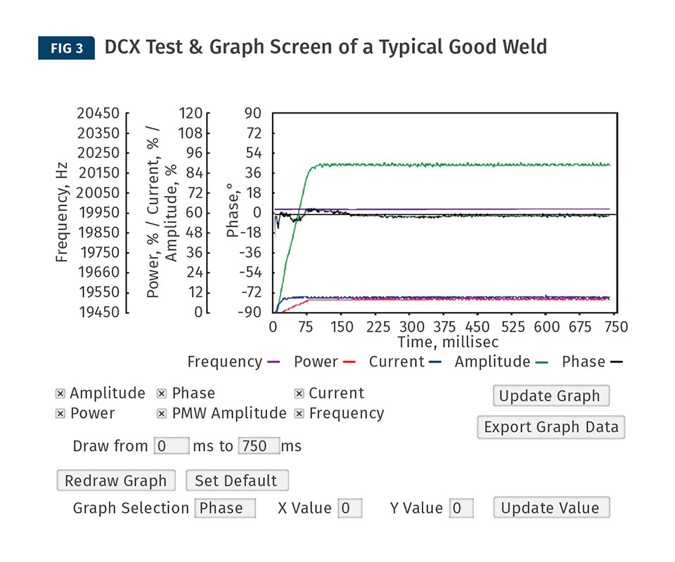
Diagnostic of a good ultrasonic weld: Within 150 millisec after weld initiation, all parameters of the weld are up to specification and continue to operate smoothly to weld conclusion.
• Weld graph data. This can help pinpoint differences between good parts and suspect parts. Data displayed on a weld graph, as seen in Fig. 3, include amplitude, current draw, power, frequency, and phase. Amplitude, phase, frequency, and current variations can indicate a problem with a power supply or stack. A discrepancy in power draw could indicate a process change (such as in weld pressure), part-geometry change (tolerances, especially in the joining area may have changed) or a stack-component problem (a horn or converter is beginning to fail).
Note that while the frequency line at center remains relatively stable, reflecting the output of the power supply, the other parameters vary wildly, as the power supply attempts to compensate for a problem farther downstream in the weld stack. In this case, it is a defective horn.
• Diagnostic scan of horn. This identifies whether the horn is drawing more power (displayed as an increase in the wattage needed to run in air). Increased power draw could indicate that a crack is forming in the horn. Such cracks are sometimes internal and therefore not always visible to the naked eye.
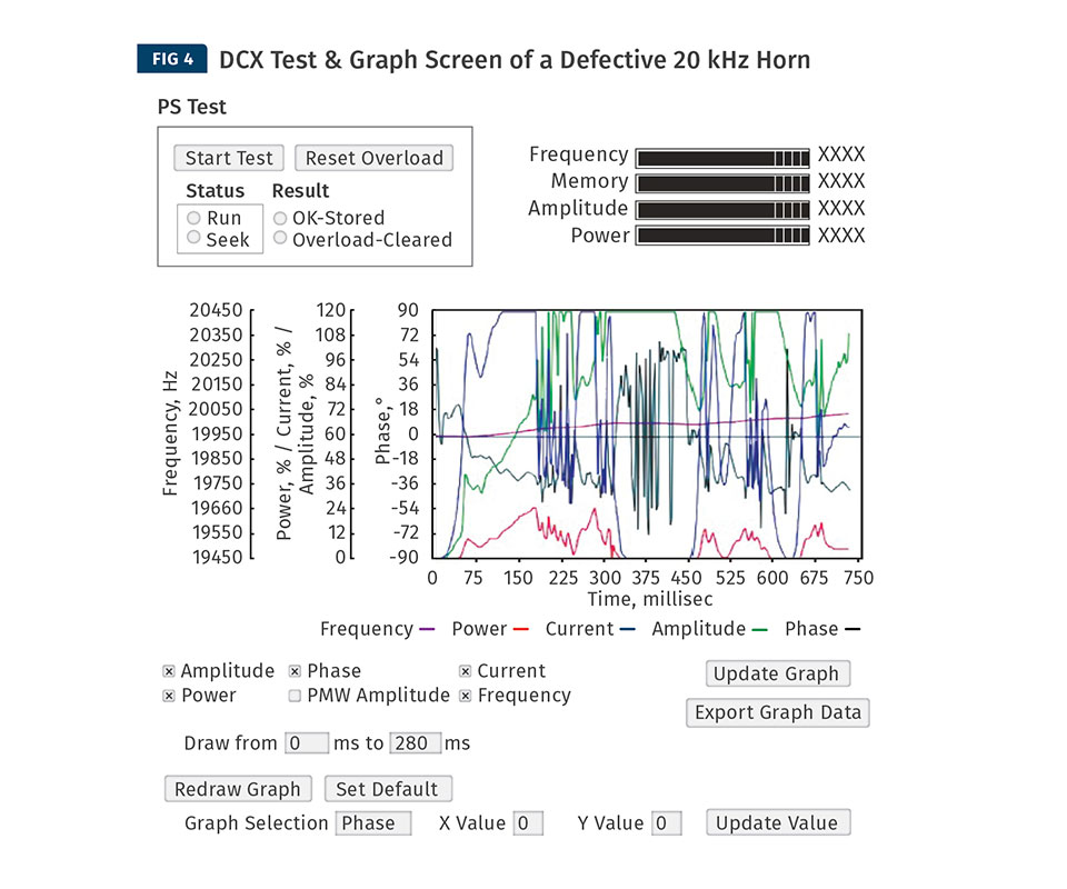
• Random data. Data that appears chaotic when compared with known, good data may indicate a fault in the converter, the horn, or in the radio-frequency cable, as seen in Fig. 4.
Process Materials & Parameters – Ultrasonic Welding
Careful control and documentation of process parameters is another area that cannot be overlooked. Medical and automotive component producers know this and follow strict procedures, often mandated by regulating agencies such as the FDA, that result in a high degree of success when using ultrasonic welding.
Unfortunately, processors of other products, such as toys or disposable products, often operate under much less stringent requirements and exercise much weaker process controls. In situations like these, it may be common for operators to continually adjust settings in response to changing part or production conditions. While this approach may result in satisfactory production, any problems that occur can be harder to diagnose, especially remotely, when process parameters vary frequently. For example, was the latest parameter change prompted by an equipment problem or a change in part composition or quality?
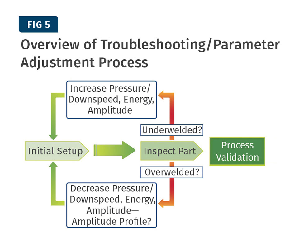
After setup, conduct an initial weld. If the weld fails inspection due to “under welding” (e.g., incomplete weld or inadequate weld depth), an increase in pressure/down speed, energy, or amplitude is probably needed. If the part is “over welded” (e.g. excessive weld depth) a decrease in the same parameters, or a diagnostic display of the weld amplitude, may be needed to identify the problem and bring the weld into specification.
Typically, when an application such as this requires assistance, an ultrasonic-welding applications engineer, after asking a few basic questions surrounding the parts (material, joint design, test requirements, and current machine setup) can direct the customer to the proper solution. This approach is especially useful if the troubleshooting can be accomplished directly at the machine, using production parts. An overview of the troubleshooting/parameter adjustment process is shown in Fig 5.
Material-related issues are a frequent source of inconsistencies or problems in production. As noted in the following examples, even slight variations in materials can have dramatic effects on weld or production quality:
• Polymer changes. As prices fluctuate, it is common for processors to want to switch between similar polymers for economic reasons. However, it is wise to consult with an ultrasonic-welding applications expert before making any changes.
One example of a common but potentially troublesome change involves moving from an easy-to-weld amorphous material such as ABS, to a much more difficult-to-weld semi-crystalline polymer, such as PP. ABS requires lower ultrasonic stack output (30-70 microns at 20 kHz) for successful welding than does PP (90-120 microns). If this change results in parts that don’t have the strength they had before, or take longer to weld, or if the welds cause damage to sensitive assembly surfaces/components, the issue could be a lack of ultrasonic stack output. An examination of stack components, particularly the horn and booster, is warranted to determine if improvements to either component will allow
the application to weld the new polymer efficiently and bring the application back to a “normal” range of success.
• High regrind content. Reground thermoplastics, though capable of being melted and reformed numerous times, undergo some degradation of their physical properties with each subsequent melt. The cumulative effect of too much reground material can lead to a failure of parts to meet specifications. For this reason, Branson recommends that no more than 10% regrind be used in parts that are to be ultrasonically welded. In specific applications that demand compliance with rigorous testing and acceptance criteria, producers should strongly consider periodic analysis of production mate- rials to continually validate the quality of mate- rials going into finished parts.
• Filler content. Often, fillers are essential to ensure part strength and durability. However, different types and percentages of fillers in parts can affect the success of plastics joining processes. Branson recommends that filler content be kept at less than 30%. Joining parts that contain a higher percentage of filler, particularly long fibers, will sometimes result in fillers accumulating at the weld joint, which can reduce weld strength.
Another issue is abrasive fillers. Some fillers that impart added strength or toughness, including calcium carbonate, silica, and talc, can also be abrasive to the contact surfaces of tooling. Prolonged exposure of abrasive parts to tooling surfaces can cause wear that could lead to cosmetic damage to parts and inadequate energy transfer to part-joining surfaces.
Changing to titanium horns with wear-resistant surfaces (carbide or titanium nitride, for example) is recommended. For fixturing, steel or hardened stainless steel is recommended.
Part Configuration & Troubleshooting
Having everything else right—equipment, materials, and process—won’t mean much if the parts you’re attempting to weld are not properly designed. But rather than try to review all of the details of a good part design here, let’s focus instead on some of the basic causes of improper part design.
Two basic causes of improper plastic part design:
- Lack of clearly defined project or application goals. Many application projects experience difficulties when there is a “moving target” for testing and acceptance. For example, will the application require a drop test? A pressure test? And if so, at what values? These values are essential to proceed effectively with the design of a sealing joint. Generally, acceptance criteria need early consideration and decision-making if a design is to proceed smoothly.
- Lack of understanding about the best joint types for particular applications. Sub-optimal joint designs often occur when a principal designer, who may only have a marginal understanding of plastics joining processes, moves a project forward only to find that an incorrect decision has been made and that part joint and weld characteristics haven’t been properly considered.
Often, such findings are made only after significant investment (mold completion, part production, and initial weld trials) has already been made. Once again, key part- and weld-related considerations (weld flash control and sealing type—hermetic, structural, or both) ought to be determined early in the project. Collaboration with an ultrasonic-welding engineer in the initial stages of a project can help to identify key part criteria, better educate designers, and help to minimize or at least illuminate possible risks.
Mold wear, usually caused by the use of abrasive polymers or fillers, can result over time in parts that are substantially and dimensionally different from earlier validated parts. As a result, principal joining features, such as energy directors or shear interference joints, are no longer within specifications. Part profiles may no longer fit properly into the tooling set. Weld results may become more and more inconsistent. The remedies for this problem include reworking the existing mold or producing a new mold.
Ultimately, issues with ultrasonically welded parts can crop up from many sources. Calling your local ultrasonic- welding equipment representative as soon as an issue is suspected could allow diagnosis and remedial tips, often accomplished via phone calls or e-mails that can help you identify, minimize, or resolve potential production problems.
To reduce the need for troubleshooting in ultrasonic welding, follow these best practices:
• Collaborate early in your project’s design (or redesign if significant material, form, or functional changes are contemplated) with your ultrasonic-welding equipment supplier’s application-engineering experts.
• Always keep a reserve of spare, production-quality components available, particularly for critical applications where production interruptions would cause significant operational or financial concerns. Spare production parts are a vital aid to troubleshooting joining problems and, in a supply pinch, can keep production rolling with a minimum of downtime.
• Take advantage of training opportunities that enable you to master the plastics joining technology you are using. Branson, for one, offers seminars at a variety of corporate locations and customer sites, providing the practical training and technical assistance needed to keep your ultrasonic process “champion” well informed about the latest technology and ready to train and maintain technology as needed in your facility. Design engineers, quality engineers, equipment maintenance personnel, and operations/production personnel can all reap benefits from time invested in training sessions.
Read More: A Step-by-Step Guide to Ultrasonic Welding
ABOUT THE AUTHOR: David Dahlstrand is Emerson's sr. regional technical coordinator/textile development engineer for Branson Ultrasonics Corp., Danbury, Conn. He has application knowledge and tooling design for ultrasonic, vibration, orbital, thermal, and laser-joining technologies used in the assembly of rigid thermoplastics, synthetic textiles, and films. Contact: (770) 962-2111, ext 17; david.dahlstrand@emerson.com; emerson.com.


Related Content

The Importance of Melt & Mold Temperature
Molders should realize how significantly process conditions can influence the final properties of the part.
Read More
A Simpler Way to Calculate Shot Size vs. Barrel Capacity
Let’s take another look at this seemingly dull but oh-so-crucial topic.
Read More
Tunnel Gates for Mold Designers, Part 1
Of all the gate types, tunnel gates are the most misunderstood. Here’s what you need to know to choose the best design for your application.
Read MoreRead Next

What Happened to Your Ultrasonic Weld Quality?
The most important factor in troubleshooting problems in ultrasonic welding is understanding the fundamentals of the process.
Read More
A Guide to Ultrasonic Welding Controls
Ultrasonic welding today is a sophisticated process that offers numerous features for precise control. Choosing from among all these options can be daunting; but this guide will help you make sense of your control features so you can approach your next welding project with the confidence of getting good results.
Read More
People 4.0 – How to Get Buy-In from Your Staff for Industry 4.0 Systems
Implementing a production monitoring system as the foundation of a ‘smart factory’ is about integrating people with new technology as much as it is about integrating machines and computers. Here are tips from a company that has gone through the process.
Read More