
Industrial CT Scanning Speeds Mold Qualification
Qualifying a mold often can take weeks and involve several costly and time-consuming steps.


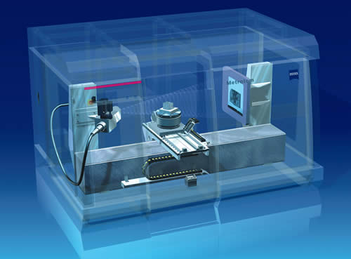
A look inside the Carl Zeiss Metrotom 1500 industrial CT scanner.
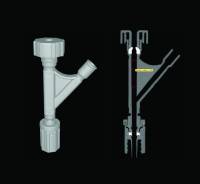
Fig.1—This shows the data set produced after x-ray scanning a medical fluid-delivery Y-connector. Immediate visual information is available, like how much the rubber grommet (bright white) is deformed by tightening the plastic threaded cap at the top of the part.
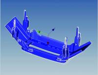
ABOVE Fig. 2—Zeiss’s Calypso measurement software aligns the measured part data to the original CAD model. CAD edge geometry is made visible to help show missing or misaligned geometry.
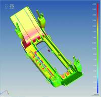
Fig. 3—The actual part geometry (inside and outside) of an automotive “PRNDL” shift selector cover after being aligned to the CAD model. Color coding is used to show variation between the two. Green areas are close to perfect, yellow-red areas show variation on the positive side of the material (+) and blue shows variation on the negative side of the material (-). The color spectrum is user-defined and values can be represented in any units. (Note: Part deviations are exaggerated here for illustrative purposes.)
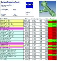
Fig. 4—CT measurement results can be reported and in a wide variety of formats, such as this Excel spreadsheet.
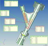
Fig. 5—Another sample of a CT measurement report. Here, the part is sliced open for visual reference and the GD&T measurement results are embedded in “balloons” that have leader lines pointing to the characteristics being evaluated. Note that balloon colors are used to show part variations from tolerance. Green balloons show characteristics that are within tolerance limits and red balloons show characteristics that are outside tolerance limits.
Qualifying a mold often can take weeks and involve several costly and time-consuming steps. With computed tomography, or CT scanning using x-rays, the time can be cut to a few days and costs can be reduced. It all starts when a new injection mold is set up in the molding machine. Everyone gathers eagerly to see the first part. The part looks reasonable but clearly leaves room for improvement.
The molding engineer proceeds to tweak the process, and after several trials a few decent parts are obtained.


Then follows the typical discovery phase, which commonly involves several different types of measuring equipment and can take up to three weeks, depending on the complexity of the part. Some companies take a statistical approach and use a Design of Experiments (DOE) methodology to zero in on optimal machine settings. A series of parts is molded with a range of machine settings defined by the DOE, so the parts will show some dimensional variation. The question is: How much variation and where?
In most cases, the tools necessary to find the variations are found in the materials and QC lab and include contact and non-contact coordinate measuring machines (CMMs) to check the part characteristics that can be seen and touched. To reveal hidden internal defects, destructive testing is performed by potting, cutting, and polishing. Yet a common complaint about destructive testing is that the evidence one is looking for is often destroyed during the process of preparing the parts. Some companies send out plastic parts for x-ray inspection to look for voids and wall-thickness variation. All of this testing often results in an expensive mold sitting idle or, worse, making parts before the qualification results are in.
CT MAKES DEFECTS VISIBLE
A faster and more accurate technology available today is computed tomography, or CT scanning. It permits internal and external analysis of a part by projecting a beam of x-rays through it while the object is rotated. It measures internal cavities, undercuts, and deep recesses not readily captured by CMMs and laser scanners, all in less than an hour, including data reconstruction.
CT is the industrial counterpart of computer-aided tomography, or CAT scanning, which uses x-rays to penetrate the body and produce a 3D image of the region of interest. The differences between CT and CAT scans lie in the x-ray energy, machine configuration, and data reconstruction algorithms. The images that are provided by CT scanning make visible any voids, cracks, and internal defects in a plastic part. This technology also does not require sophisticated fixtures, therefore eliminating part distortion from clamping forces.
CT scanning is used in the medical, electronics, aerospace, and automotive industries for materials evaluation, prototyping, and quality control. Depending on physical size and x-ray penetrating power, industrial CT systems can cost from $300,000 to $5 million. For companies that don’t need their own full-time CT scanner, scanning services are available to make CT inspection affordable.
Carl Zeiss supplies CT scanners and newly offers scanning services using its Metrotom CT scanner. This unit can scan parts that fit into a cylindrical volume of 350 mm (13.65 in.) diam. x 350 mm high and weigh a maximum of 51 kg (112 lb). Zeiss also offers scanning services using a larger Varian BIR 450kV scanner for defect detection in large components like plastic chairs. It can handle parts that fit into a cylindrical volume of 520 mm (20.3 in.) diam. x 1200 mm (46.8 in.) high and weigh up to 100 kg (220 lb).
(Editor’s note: A few other companies offer such a service—such as Varian Medical Systems, Palo Alto, Calif., and Bolton Works, E. Hartford, Conn.).
NEW LEVEL OF CT SCANNING
The Zeiss Metrotom 1500 computer tomograph represents a new level of industrial CT scanning measurement technology. Dubbed “metrotomography,” it was developed specifically to allow comprehensive quality assurance. Unlike standard industrial CT scanning procedures, metrotomography goes beyond pure visual inspection and offers the possibility of also measuring the internal and external geometries of highly complex parts. If the parts are small enough, as is the case with some medical devices, it can scan multiple parts simultaneously.
The Metrotom was designed from the ground up, using technology from Zeiss’s high-performance CMMs, such as the guide ways, drive systems, controller, rotary table, and Calypso metrology software. The result is a non-destructive testing system that is very accurate—down to 9 microns for typical plastic parts—and extremely repeatable, as it will pass Gage Repeatability and Reproducibility (GR&R) tests. Metrotom also uses software that can evaluate ANSI (American National Standards Institute) Y14.5 GD&T drawing standards.
HOW IT WORKS
A part is placed on a rotary table in the x-ray scanning chamber. After one full revolution, which takes 30 to 60 min, the system produces a complete 3D data sheet (see Fig. 1). In contrast to typical industrial CT systems, there is no need for data manipulation or scaling, because Metrotom produces a data set with an MPEE of +9+L/50 microns everywhere inside and outside the part. MPEE is the ISO gauging industry acronym for Maximum Permissible Error and is a statement of traceable system measurement uncertainty.
In the next step, the Zeiss Calypso measurement software aligns the part dataset to the CAD model of the part using the datum reference frame (DRF) specified in the part drawing (Fig.2). Once aligned, the only visual indication that a CAD model is overlaying the CT dataset is the CAD surface edges that reveal the underlying geometry. This software tool can help to quickly identify small features in the plastic that were not properly filled out (short shot) and may often go unnoticed, due to their size or hidden location. Calypso software takes part measurements directly from the CT grayscale image models rather than the STL data format used by popular stereolithography or other rapid-prototyping systems. STL format was developed for visualization purposes but was never intended to represent an exact description of the part geometry.
With the data set aligned with the CAD model, the analysis begins. A very practical and fast first step is to show graphically, via color variation, where all the internal and external surfaces differ from the CAD model (Fig. 3). To look even deeper inside the part, software tools are available to provide a cross-section from any orientation. This cross-sectioning tool can also be used to reveal voids inside the material. Not only is color used to show a deviation from the CAD model, but it can easily be used as a go/no-go gauge.
The scanning and analysis described thus far take place in a few hours. The color maps are useful to helped to zero in on the injection molding issues. But what you really need is a full layout report. With Calypso software, tools are available to develop a measurement plan for complex plastic parts such as the fluid-delivery valve in Fig. 1.
With its Geometric Dimensioning and Tolerancing (GD&T) math engine, Calypso software can handle your GD&T call-outs and report the data in a wide variety of formats. A Microsoft Excel output report and “balloon diagram” with leaders pointing to the characteristics in question are illustrated in Figs. 4 and 5, respectively.
THINGS TO CONSIDER
Whether you are looking to buy a CT scanner or exploring the advantages of a scanning service, consider the following:
- Accuracy: Resolution is not the same as accuracy. High resolution can never compensate for poor electromechanical design of a measuring instrument. Systems intended to be used for precise measurement must be qualified against known reference standards. Ask the manufacturer and/or service provider to show you how they qualify the accuracy of their CT systems.
- Repeatability: When evaluating a new gauging system, take the time to confirm that the system is capable—i.e., repeatable and free from operator influence. One of the “gold standards” for judging system capability is a GR&R. A good rule of thumb is that the gauge must repeat to 3% of the characteristic tolerance to achieve a 105 GR&R.
- Speed: The goal is to qualify new molds in a day—not a week or more.
- Software: Even a fast, accurate, and repeatable system is useless without software tools that can provide meaningful results. Metrology software must be able to import any CAD format, have a strong Geometric Dimensioning & Tolerancing (GD&T) math engine, offer a fast way to create and edit measurement plans, and— most important—be able to measure from a native CT grayscale data set.
ABOUT THE AUTHOR
Kevin Legacy is manager of computed tomography and engineering at Carl Zeiss Industrial Measurement Technology (IMT) Corp., Maple Grove, Minn. He has been with the company for 11 years and held various sales and engineering management positions. He can be reached at klegacy@zeiss.com or (248) 867-3699. For more information on Zeiss, visit www.zeiss.com/imt.


Related Content

Try This Alternate Method for Heating Your Torque Rheometer
Rheometers are generally not on all the time. And most users have found that the first test run in the instrument after heating up is not very reliable and is usually discarded. Try this method instead.
Read More
How to Improve Quality with Offline Inspection and Analysis
Automated sample testing with a light table detects the smallest contamination in flakes, micro granulates and sample test sheets.
Read More
How Inline Vision Inspection Can Minimize Scrap in Molding
Once viewed by injection and blow molders as a necessary evil, machine vision technology today can continuously monitor and improve production while reducing costs.
Read More
Datacolor Acquires Matchmycolor
The acquisition of the specialist in color formulation and communication software further expands Datacolor’s global industry presence in color management.
Read MoreRead Next

Troubleshooting Screw and Barrel Wear in Extrusion
Extruder screws and barrels will wear over time. If you are seeing a reduction in specific rate and higher discharge temperatures, wear is the likely culprit.
Read More
Lead the Conversation, Change the Conversation
Coverage of single-use plastics can be both misleading and demoralizing. Here are 10 tips for changing the perception of the plastics industry at your company and in your community.
Read More