
IR Thermal Imaging Diagnoses Part Defects
Ability to monitor and modify the surface temperature of a heated sheet is critical to making high-quality thermoformed parts.


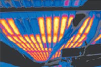
IR thermal imaging can reveal oven heater problems. Here, a three-heater bank at upper left has clearly failed.
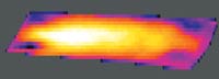
Thermogram of heated PVC sheet shows deliberate non-uniform or “profile heating” of the sheet. Cooler sections at the corners are intended to control drawdown in those locations
Ability to monitor and modify the surface temperature of a heated sheet is critical to making high-quality thermoformed parts. In most cases, thermoformers prefer to work with sheet that is heated to create a highly uniform temperature distribution across both the X and Y dimensions of the surface (and hopefully the core) of the sheet. But in other instances, such as with difficult materials or highly complex parts, it may be more beneficial to use “pattern” or “profile” heating—i.e., to intentionally vary temperature contours across the sheet in ways that make better and more consistent parts.
The need to accurately control sheet temperatures is prompting growing interest in infrared (IR) imaging. This non-contact technology uses an IR line scanner to rapidly scan and read temperature at countless points over the entire surface of a two-dimensional sheet. The resultant thermal contours are then color-mapped, with colder sections shown in black or blue and hotter zones portrayed in white, yellow, or orange. Software allows a grid representing the heaters and heating zones of a specific thermoforming machine to be superimposed on the thermal map (thermogram) of the sheet.


Radiant heat, being fast-acting and energy-efficient, is the most widely used method for thermoforming ovens. However, maintaining a constant temperature at each heater is by no means sufficient to guarantee sheet-temperature uniformity. For one thing, edges of the sheet generally receive less energy than center portions do, so heaters at the center would have to operate at lower output in order to get a thermal balance. Moreover, both sheet dimensions and the distance of the sheet from any given heater’s surface also cause sheet surface temperatures to vary.
Meanwhile, failure to compensate for these variations is likely to increase part defect rates. Typically, there is an upper temperature limit for a sheet, and when that is exceeded, defects like blistering, scorching, color change, wrinkling, and sheet sagging are almost certain to multiply (see table).
Another dilemma arises from the goal of maximizing productivity. One way is to reduce the heating time and compensate by increasing heater temperature to arrive at the normal forming temperature faster. The danger is that the material’s upper temperature limit will be exceeded more often than not, causing part defects to rise. Resin suppliers have incorporated improved heat stabilizers to neutralize this effect. Yet thermoformers face an inevitable trade-off between maximizing throughput and minimizing the part defect count and scrap rate.
Using IRimaging
Temperature-induced part defects result primarily from sheet being too hot or too cold. In the past, corrective action has usually involved machine and heater adjustments requiring numerous trial-and-error tests, at a cost of much wasted time, labor, and material.
In contrast, defects can be detected and corrected more quickly and economically with thermal imaging. Typically, the IR line scanner is placed between oven and forming station, providing a temperature map as sheet exits the oven. This gives the operator “a new set of eyes” for visualizing sheet temperatures, which facilitates early detection of defects and allows for speedy corrective action without interrupting production.
Real-life examples
Thermal imaging’s potential for enhancing process efficiency and part quality in thermoforming is best illustrated with examples. In one case, a continuous roll-fed, in-line thermoformer had been incurring high defect levels for reasons difficult to determine. Thermal imaging revealed the existence of cold spots stemming from two sources. One was due to part of the sheet not being fully inside the oven during the indexing cycle. Also, undetected air drafts were penetrating into the oven. Correction involved adjusting heaters in the affected zones in accordance with data provided by the thermal images.
second example involved a complex PVC part being run on a cut-sheet rotary unit (see photo at right). In this part, non-uniform profile heating of the sheet was necessary to modify thermoforming behavior. The need was to make corner areas of the molten sheet colder than areas at the center, thereby ensuring improved control of draw and more uniform wall thickness. The thermal maps proved indispensable in establishing the heating profile and keeping it constant.
Yet another role for thermal imaging is preventive maintenance of parts used in the oven, notably heaters (see first photo). Heater failure is usually discovered only after a large number of defective parts have been run. Processors are advised to run thermal scans of the ovens and heaters on a periodic basis to detect heater burnouts, malfunctions, and early signs of potential failure.
Meanwhile, in custom cut-sheet forming, infrared scanners are also proving effective in reducing set-up times, proving out new tools, and assisting design of new products.
Payback on the initial cost of a thermal imaging system typically occurs in less than a year. Raytek’s TF100 system, including the MP50 Process Imager and necessary software and auxiliaries, is priced at $13,750 to $16,250. Thermoformers currently using thermal imaging systems include Associated Thermoforming in Bethoud, Colo., and Aircraft Technologies in San Antonio, Texas.
Dr. Alan Young is product market manager for Process Imaging Systems at Raytek Corp.’s Automation Div. in Santa Cruz, Calif. He has worked for almost 30 years to develop non-contact measurement and sensing devices for paper, textiles, sheet metal, plastics extrusion, and thermoforming. He can be contacted at alany@raytek.com.


Related Content

Ingenuity Is Part of This Former’s Name, and in Its DNA
Plastic Ingenuity started in a garage in 1972 and through a commitment to developing best-in-class products stands today as one of the largest custom thermoformers in the world.
Read More
Thermoforming PCR: An Equipment Supplier’s Pointers
Thermoforming PCR is not radically different from forming virgin, but variation in recycled materials can require extra care to get a consistent end result. Start by examining every aspect of the process from the sheet (and extrusion process if run inline) to the final trim.
Read More
Cobot Creates 'Cell Manufacturing Dream' for Thermoformer
Kal Plastics deploys Universal Robot trimming cobot for a fraction of the cost and lead time of a CNC machine, cuts trimming time nearly in half and reduces late shipments to under 1% — all while improving employee safety and growth opportunities.
Read More
OMV Technologies Gets New CEO
Kooper brings 33 years of experience in the industrial and consumer packaging industries to OMV--the closed-loop, turnkey, inline extrusion, thermoforming and tooling systems manufacturer.
Read MoreRead Next

How Polymer Melts in Single-Screw Extruders
Understanding how polymer melts in a single-screw extruder could help you optimize your screw design to eliminate defect-causing solid polymer fragments.
Read More
Understanding Melting in Single-Screw Extruders
You can better visualize the melting process by “flipping” the observation point so that the barrel appears to be turning clockwise around a stationary screw.
Read More