
Know Your Options in Valve-Gated Hot Runners
Valve-gated hot-runner systems have been used for almost 50 years as a way to efficiently mold large parts.
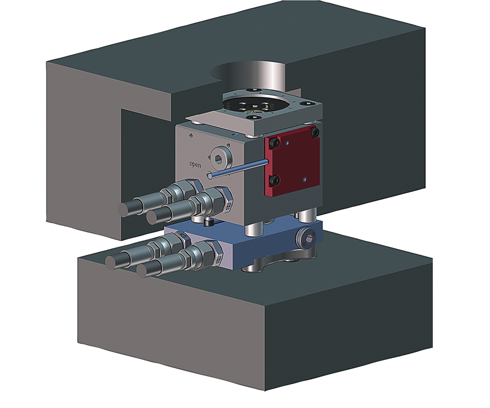
Water-cooled isolation plate between the actuator and the hot manifold protects actuator from the heat of the manifold.
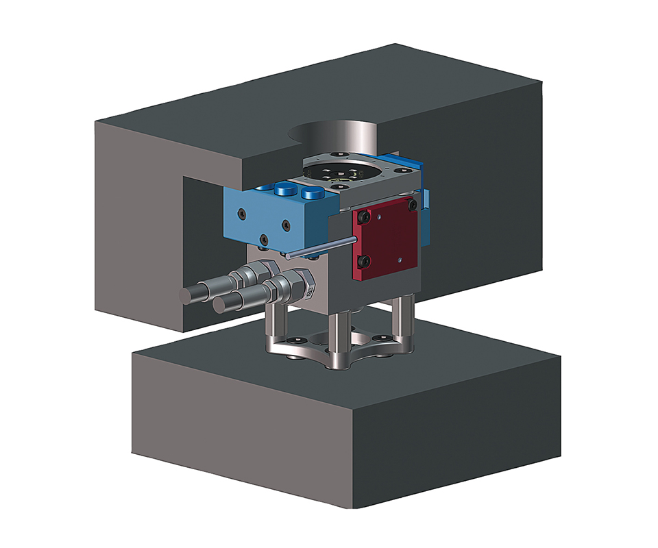
Passive cooling devices (shown in blue) make contact with the cooled top mold plate, preventing the actuator from overheating. In many applications these passive cooling devices can eliminate the need for water-cooled isolation plates.
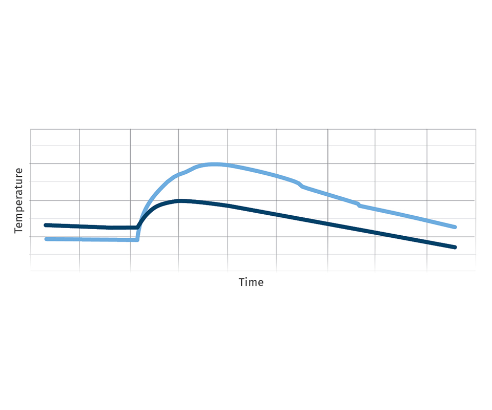
The light blue line shows the temperature of an actuator with a water-cooled isolation plate when the cooling water is turned off at the same time as the hot-runner heats. The darker blue line shows the temperature of an actuator with a passive cooling device under the same circumstance. The actuator that depends on the water-cooled plate overheats while the actuator with the passive cooling device stays cooler.
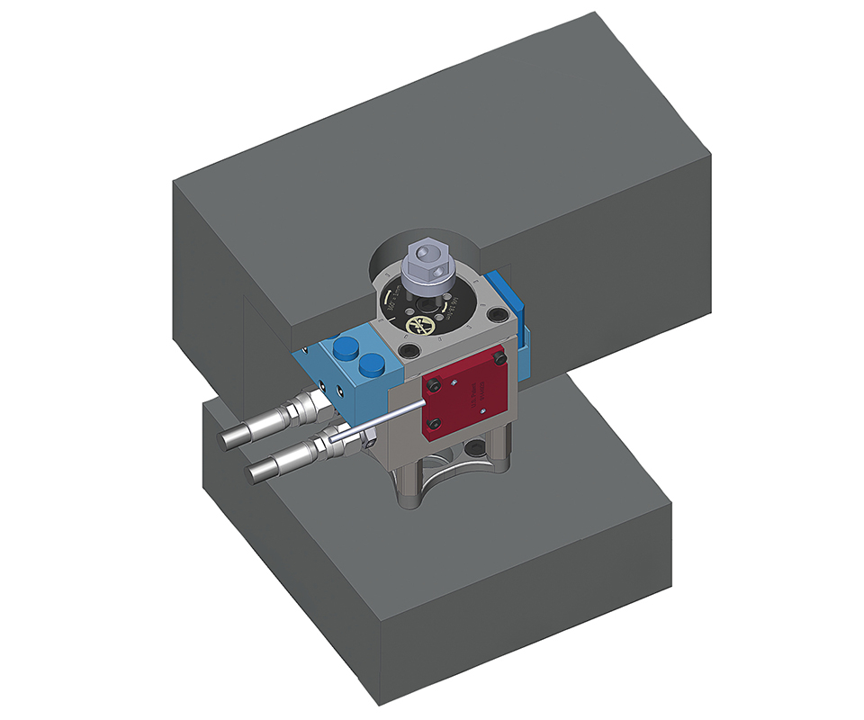
Instead of adjusting the valve-pin position with shims, the effective pin length can be changed with a simple turn, using a tool through a hole in the top clamp plate.
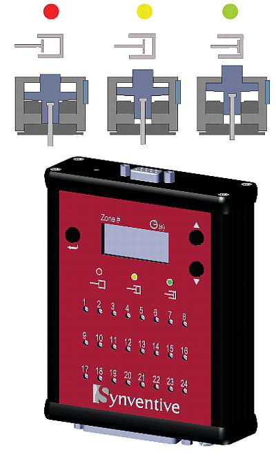
Simple devices can show remotely the current status of each pin, making troubleshooting both faster and safer.


Valve-gated hot-runner systems have been used for almost 50 years as a way to efficiently mold large parts. At first they were considered an expensive and complicated alternative to thermal gates and were only used when absolutely necessary. Over time they have become more and more common, to the point where in many markets they are the norm, not the exception. Valve gates allow molders to eliminate gate vestige, decrease cycle times, and manipulate the filling of various gates during the injection cycle.
As with any technology, advances have been made over time. In fact, recent years have resulted in some of the most significant technology gains. Valve-gate actuators began as simple pistons connected to a valve pin, allowing molders to open and close the hot-runner gates at a time of their choosing. The actuators used to drive the pins have become much more advanced, providing the molder and tool-shop personnel with a variety of abilities and benefits they did not have previously.


Actuators fall into two categories with respect to how they mount in the tool: in-plate and bolt-on. In-plate actuators fit into pockets machined in the top clamp plate, while bolt-on actuators bolt directly to the hot-runner manifold. In-plate actuators are typically installed into the top clamp plate by the tool maker after the remainder of the “A” half of the mold has been assembled.
Bolt-on actuators allow the hot runner to be supplied to the mold maker as a preassembled and tested drop-in system, complete with hydraulic disconnects, so that no plumbing is necessary during installation. These systems also can be removed as a unit and tested outside of the tool, making troubleshooting and maintenance much easier.
One of the disadvantages of bolt-on actuators is they need to be cooled to protect them from the heat of the manifold. The common solution to this challenge has been to run water-cooled isolation plates between the hot manifold and the actuator. The water-supply lines for these plates add complexity to the drop-in system and take up further space in the mold. These water-cooled isolation plates are only effective when the water is circulating.
Frequently at the end of production, the cooling water to the mold is turned off at the same time as the hot-runner temperature controller. Large manifolds will take hours to cool down, thus transferring heat into the actuators, which are no longer receiving the benefit of the cooling water. This excessive heat can prematurely degrade the seals in the actuator as well as the hydraulic fluid in the case of hydraulic systems. Impurities in the water can collect over time inside the cooling plates and at the connection of the water lines, restricting the water flow and making the cooling plates less effective.
BEAT THE HEAT
Bolt-on actuators are now available with passive cooling devices, which are designed to transfer excessive heat out of the actuator and into the top clamp plate. These devices prevent the actuator from overheating when the cooling water is turned off at the same time as the hot-runner heats (see graph on opposite page). In many cases, they can even eliminate the need for dedicated cooling lines to the actuator. This greatly simplifies the hot-runner system and can save a significant amount of space inside the tool, helping with tool support. Eliminating the water-cooled plates also reduces the water connections on the side of the tool, where space is often at a premium.
Pin-height adjustment is another area where newer designs can greatly benefit the tool maker. In early actuators, adjusting the final forward pin position in the gate was done by adding and removing shims behind and in front of the valve-pin head. With that style of actuator, adjusting the pin position can be a time-consuming process. Many actuators today have the capability to adjust the pin height with a simple turn of an adjustment mechanism. In some designs this can even be done through the top clamp plate with the tool completely assembled, making pin-height adjustments a simple process requiring no disassembly of the mold or the actuator.
Quick valve-pin decoupling is another feature that sets newer actuators apart from their simpler predecessors. In many of the older-design actuators, the pin is locked into the piston, requiring both the pin and the actuator to be removed as a unit. In other designs, it is necessary to disassemble the actuator to separate it from the valve pin. New designs are now available that incorporate quick-decouple features, allowing the pin and actuator to be separated easily without having to remove one to remove the other. This saves a great deal of time and preserves the pin adjustment when maintenance is required for either the tool or the hot-runner system.
Today, actuators can be hydraulically, pneumatically, or electrically powered. Because of the availability of high pressures when running hydraulics, hydraulic actuators can be small yet powerful. Pneumatic actuators need to be larger because of the much lower pressure typically available with air, but are generally considered cleaner than hydraulics. Electric actuators offer a clean option and some even have the ability to adjust the pin’s speed and stroke, unlike conventional hydraulic and pneumatic actuators.
Hydraulic actuators are most commonly used in larger applications where large pins need to be moved against high injection pressures, and therefore high forces are required to move the pin quickly. These actuators are very responsive as long as there is no air in the hydraulic circuit. As a result, it is necessary to completely bleed the air out of the hydraulic lines and the actuator piston itself in order to realize maximum performance. Bleeding is obviously necessary when a new system is assembled, but just the act of disconnecting and reconnecting the hydraulic hoses during the life of the tool can introduce air into the system, requiring periodic bleeding for maximum responsiveness.
Many newer hydraulic actuators have built-in self-bleeding mechanisms that completely eliminate the need to bleed the system after initial installation or at any time during the life of the tool. These self-bleeding actuators save tooling personnel time over the life of the tool and eliminate scrap caused by sluggish valve pins.
BENEFITS OF POSITION SENSORS
Probably the most significant of the recent advances to both hydraulic and pneumatic hot-runner actuators is the option of adding a position sensor. Simple position sensors can now be added to these actuators, which can later be combined with flow-control technologies yielding all the same control benefits of an electric actuator.
Systems that have actuators with position sensors can be hooked to simple monitoring devices. These devices can give feedback on the current position of the pin as well as the amount of time the pin takes to complete a movement. This is a great diagnostic tool to ensure that all connections are made properly after a mold is installed in the press. With large molds, especially those with deep cavities, it is impossible to see the pins move from outside the press, even when the mold is open. It is not uncommon for an operator to stand inside the press in order to confirm that the pins are moving correctly and that they correspond to the appropriate zones on the controller. External pin-position monitoring devices can eliminate this dangerous practice.
The greatest advantage of having position sensors on the actuator is that they allow the hot runner to be used with flow-control technologies after it has been determined that there is in fact a need for additional control. There are many types of flow-control technologies available today that allow the molder to manipulate the movement of the valve pins.
Some technologies slow the movement of the pin for the entire stroke. Others give the molder the option of defining a reduced speed as well as a distance over which that reduced speed will be maintained before returning to full speed. Technologies that control the opening speed of the valve pin help eliminate visible pressure lines in the part commonly caused by the sudden shifting of the pins while the manifold is pressurized.
Other technologies provide full pin-position control, allowing the molder to fully define the velocity, acceleration, and stroke of each pin. These types of control technologies offer the molder with hydraulic or pneumatic actuators the same pin-control capabilities available with some electric actuators. They provide the same capabilities as the monitoring and controlled open-speed technologies but can also allow the molder to balance tools, fill extremely complex multi-gated parts, reduce warpage, cut clamp force, and even trim part weight. All of this additional control can be added after the fact, as long as a position sensor is added to the pneumatic or hydraulic actuator when the tool is built.
The advantage of this upgradeable approach offered by pin-position sensors cannot be overstated. If a molder wishes to use an electric system to gain pin control, it must commit to the technology at the time of the tool build. Once the tool is built, the system cannot be run without the special electric valve-gate controller. If the hot runner is sent back to the mold maker for maintenance that requires the pins to be actuated, the electric valve-gate controller must be sent with it or the mold maker will not be able to move the pins unless they own the corresponding controller.
An injection molding machine interface is also required on the press, because the controller that handles the sequencing of the electric valve pins, needs to communicate with the molding machine in order to operate properly. This can be an issue when a decision is made to move the mold to a different machine or molding plant on short notice.
With hydraulic or pneumatic actuators that have position sensors, it is often possible to purchase just the base system with the sensors and test the mold conventionally first. Once parts are molded, it can then be decided if the process would benefit from further pin control. The necessary flow-control equipment can be added after the fact.
Although special equipment is required to run with the new pin-control capabilities, the mold can still be run conventionally without the equipment. This allows the molder to determine after the first shots whether the financial investment for the additional equipment is necessary and avoid being “handcuffed” to the technology for the life of the tool.
ABOUT THE AUTHOR
Bill Rousseau is director of applications and technical services at Synventive Molding Solutions, a business of Barnes Group Inc. in Peabody, Mass. He has a Master’s Degree in Plastics Engineering from the University of Massachusetts—Lowell and more than 20 years’ experience in the plastics industry, most of them dedicated to hot-runner technology. Contact: (800) 367-5662; brousseau@synventive.com; synventive.com.


Related Content

How to Select the Right Tool Steel for Mold Cavities
With cavity steel or alloy selection there are many variables that can dictate the best option.
Read More
Why Shoulder Bolts Are Too Important to Ignore (Part 1)
These humble but essential fasteners used in injection molds are known by various names and used for a number of purposes.
Read More
Back to Basics on Mold Venting (Part 2: Shape, Dimensions, Details)
Here’s how to get the most out of your stationary mold vents.
Read More
How to Optimize Pack & Hold Times for Hot-Runner & Valve-Gated Molds
Applying a scientific method to what is typically a trial-and-error process. Part 2 of 2.
Read MoreRead Next

How Polymer Melts in Single-Screw Extruders
Understanding how polymer melts in a single-screw extruder could help you optimize your screw design to eliminate defect-causing solid polymer fragments.
Read More
Lead the Conversation, Change the Conversation
Coverage of single-use plastics can be both misleading and demoralizing. Here are 10 tips for changing the perception of the plastics industry at your company and in your community.
Read More
Understanding Melting in Single-Screw Extruders
You can better visualize the melting process by “flipping” the observation point so that the barrel appears to be turning clockwise around a stationary screw.
Read More