
Laser Scanning Pinpoints Shrinkage Problems in Record Time
A faster way to measure part surface dimensions helped injection molder Hy-Ten Plastics to quickly identify and correct geometries in its tooling that spawned problem parts.


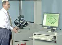
Laser Design's laser scanner maps surface dimensions of a molded part more quickly and accurately than a CMM.
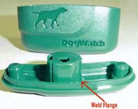
CAD data and flow simulation weren't enough to provide exact guidance on mold-design changes needed to overcome shrinkage distortion along the critical weld flange.
A faster way to measure part surface dimensions helped injection molder Hy-Ten Plastics to quickly identify and correct geometries in its tooling that spawned problem parts. Hy-Ten, a $5-million/yr company in Milford, N.H., is no stranger to challenging molding projects, yet it needed help to deliver one project on time. The company molded parts for a dog-collar signal-sensing system sold by DogWatch of Natick, Mass. The DogWatch System 3000 consists of a small electronic device that hangs from a dog collar and emits an FM signal to stationary receivers. An alarm sounds when the dog-collar emitter passes a receiver. The system creates a “hidden fence” for the dog.


Shrinkage problems
Two-piece housings for the dog-collar transmitter and the signal receiver are molded by Hy-Ten using a high-flow polycarbonate. The challenge was in producing the four-parts in a 2 x 2 family mold. The critical requirement was a very precise interference fit between each of the molded halves, which would be ultrasonically welded together to provide a water-tight seal around the electronic components. “The geometry of the parts was so complex that the parts shrank in a very non-uniform and hard-to-predict manner,” says Craig Heinselman, quality-assurance manager for Hy-Ten.
Irregular shrinkage caused the prototypes to fit together unevenly. “Because of the complex 3D geometry, the only way to design the mold was to guess at the shrinkage, build the mold, and measure the parts,” Heinselman said.
Through early trials Hy-Ten had eliminated the material, mold cooling, and process parameters like fill times and speeds and packing pressures as sources of the problem, so that narrowed the focus to the design of the core or cavity.
The CAD/CAM software that Hy-Ten uses for part and mold design couldn’t provide enough help on how to correct the problems, and flow-simulation only gave an estimation of the deviation of the part dimensions due to shrinkage. “We needed to know the degree to which the part actually deformed,” says Heinselman.
To solve such a problem, Hy-Ten would usually employ a coordinate measuring machine (CMM) to “map out” the shape of the parts by measuring positions on the part surface point by point. That surface map would then be compared with the “ideal” part dimensions specified in the CAD model, and the differences would give insight on where and how much to adjust the core or cavity dimensions. “Yet when you are dealing with a complex 3D contour, you often need millions or tens of millions of points to get the geometry exactly right. We could have easily spent several weeks generating the points on the parts, and even then we would not have been sure that we didn’t miss points that were necessary to get an accurate surface model,” says Heinselman.
The other big problem was time. Hy-Ten had promised its customer that part samples would be delivered for their review and approval within a month. This left too little time to generate the CMM plot, analyze the part differences, send the suggested mold changes to the tool maker, and then get the mold back to produce parts.
Laser scan to the rescue
Hy-Ten enlisted the services of Laser Design, a Minneapolis service bureau that uses laser scanning to map part geometry. Laser Design took just five days to create a surface model of each prototype part that was accurate to 0.001 in., and to map it onto the original part geometry, creating an “error map.” The error map made it easy to modify the mold so that the final parts shrank to the correct size and shape. It took the tool maker just nine days to adjust the tool based on the error map, and six more days for Hy-Ten to produce the new sample parts. “What had taken 20 days would have taken months of expensive trial and error using conventional means,” says Heinselman.
Laser Design employs a non-contact, low-power diode laser system to measure the parts, says Larry Carlberg, engineering service bureau manager. The system casts a laser beam across a surface and picks up or assigns anywhere from 15,000 to 50,000 points per second. The laser can plot 10 million to 20 million points, but an accurate analysis requires only 1 million to 5 million points. “A part that is 6 in. square can be scanned on both sides in 15 to 25 minutes and be accurate to ±20 microns,” says Carlberg.
The points are transmitted to a software package from Raindrop Geomagic of Raleigh, N.C. The Geomagic Qualify software generates the detailed dimensions of the part and compares them to the original CAD design. It creates a color map that shows the deviation of the part surfaces between the two sources. “Laser scanning delivered higher-quality parts in a fraction of the time of CMM and helped us determine precisely how the prototype differed from the design intent,” says Carlberg.
Once Hy-Ten received the color map from Laser Design, it sent the suggested changes to the mold maker, Concept Tool and Die in Goffstown, N.H.
A laser scanning system and software would cost around $115,000 to $150,000, says Carlberg. A portable laser probe that is retrofittable to a CMM machine would cost around $60,000. However, Laser Design’s service cost around $600 for each part scan (price varies with part design and number of plot points required), including an inspection report.


Related Content

Robust Rotational Viscometer
Versatile viscometer line said to offer robust measurement, repeatability and reporting.
Read More
How to Improve Quality with Offline Inspection and Analysis
Automated sample testing with a light table detects the smallest contamination in flakes, micro granulates and sample test sheets.
Read More
Fast, Simple QC Method Directly Quantifies Recycled Content in Plastics
Novel fluorescence-based spin-out technology provides a rapid and reliable method to measure and certify recycled content in a wide range of plastics.
Read More
Datacolor Acquires Matchmycolor
The acquisition of the specialist in color formulation and communication software further expands Datacolor’s global industry presence in color management.
Read MoreRead Next

Understanding Melting in Single-Screw Extruders
You can better visualize the melting process by “flipping” the observation point so that the barrel appears to be turning clockwise around a stationary screw.
Read More
How Polymer Melts in Single-Screw Extruders
Understanding how polymer melts in a single-screw extruder could help you optimize your screw design to eliminate defect-causing solid polymer fragments.
Read More
Processor Turns to AI to Help Keep Machines Humming
At captive processor McConkey, a new generation of artificial intelligence models, highlighted by ChatGPT, is helping it wade through the shortage of skilled labor and keep its production lines churning out good parts.
Read More