
Micro Molds Make Micro Parts
Molded parts barely visible to the naked eye require non-traditional methods for making high-precision micro-injection molds. Micro-tooling R&D is being led by technology institutes, research firms, and a few highly specialized mold makers.


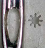
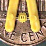
Eye of the needle: New moldmaking technologies meet growing demand for micro-scale parts. This nickel cobalt tool is made with a uv-lithography process from Mimotec. The nylon gear cavity is 0.48 mm in diam. with a tooth wall section of 0.066 mm.
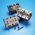
Micro tools can accommodate two-shot molding. Makuta uses this shuttling mold to produce a small ABS part with raised lettering in a second color. The letters are only 0.25 mm wide.
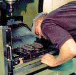
Sometimes it requires a microscope to see what's happening when micro-machining tiny features in tools for micro parts. The features are so small that special milling machines are being developed with motion steps just 1/100th as large as standard machines. (Photo: MTD)
Tiny features: This 0.0017-gLDPE piezoelectric sensor has a pair of 3-mil slots and a 5-mil rib—each a shutoff—as well as 2-mil edge gates on either side. (Photo: MTD)
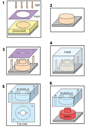
Mimotec's LIGA micro-tooling process is a lithography method previously used for semiconductors: (1) Epoxy resin is selectively cured by uv light beamed through a mask. (2) Uncured epoxy is etched away. (3) Subsequent masking steps produce additional features. (4) Metal is then electroformed over the cured epoxy to form a mold half. (5) The metal mold is ground to the correct height, and the epoxy is dissolved away, leaving a cavity and ejector holes. (6) The tool is ready to mold parts.
It's no small trick to design and build molds with cavities the size of a vent hole and details best viewed through a microscope. However, considerable progress has been made in producing tooling for the production of millimeter- and micron-sized parts to meet growing demand from the biomedical, pharmaceutical, fiber- optic, electronics, telecommunications, office-automation, computer, and automotive fields. "Demand is getting bigger, and the size of the parts is getting ever smaller," says Ron Peterson, general manager at Micromold Inc., an injection molder in Riverside, Calif. "Some parts being molded today are so small that a 0.005-in. imperfection would appear as large as some of the molded features on the part."
"A few years ago, conventional tool makers laughed at the idea of micro-molding applications and at the tooling specifications needed for production," says Phillip Leopold, president of Murray Inc., which makes a micro-injection press for molding parts the size of sesame seeds. Some of these parts involve overmolding with combinations as exotic as PEEK and silicone rubber in two separate molds or even in one tool.


Another firm, Miniature Tool and Die (MTD), is creating micro molds for parts just 0.060 in. long with wall thicknesses down to 0.0015 in. and weighing as little as 0.00013 g. "This equates to 520 parts per pellet," says Donna Bibber, v.p. of sales and marketing. Molds for such parts use gate sizes down to 0.002 in. and core pins of only 0.0045 in. diam.
To meet the micro-molding challenge, tool builders are taking conventional mold-making technologies such as milling and electrical discharge machining (EDM) into unfamiliar territory and are exploring new methods as well. One firm has harnessed a technology used in the semiconductor and watchmaking industries for the production of micro molds.
Some of the leading developers are foreign based, such as Mimotec S.A. of Switzerland, which has developed a technology that uses uv light and electroplating to create tooling components. Sansyu Precision of Japan uses proprietary micro-milling techniques to create micro molds for its sister molding firm, Makuta Technics, which has a plant in Columbus, Ind. R&D in micro-milling, EDM, and laser techniques is taking place at the German and Boston campuses of the Fraunhofer Institute, which also has developed a brand-new approach that combines milling and electroplating. In the U.S., MTD appears to be one of the strongest promoters of micro-tooling technology. It employs special EDM techniques to create micro-miniature cores and cavities.
The various micro-tooling technologies can be characterized by the feature dimensions they typically can attain, the achievable part aspect ratios (height/width), the materials used to form the core and cavity, level of precision, strength and durability, and speed of production of the mold, says Dr. Luz Weber, managing director of thinXXS Microtechnology, a spin-off of the Institute of Microtechnology Mainz in Mainz, Germany. The factors he cites can vary widely from process to process and can yield quite a different range of micro parts.
ThinXXS is developing and using many technologies capable of producing micro-molded components, and is gaining expertise on the ins and outs of each approach. ThinXXS has eight process techniques in evaluation at its facility, spanning both conventional technologies and more exotic or developmental techniques. The roster includes ultra-precision milling, EDM, laser ablation, silicon micro-machining, electroplating, uv or x-ray lithography, and electron-beam (e-beam) lithography. These techniques generate typical feature dimensions from 0.5 to 1000 microns, depending on the process, and aspect ratios from 1 to 100. Materials of construction range from hardened steels to nickel, nickel alloys, and even silicon.
No small challenge
Micro-mold designers and builders have to contend with a number of critical issues. "Parting-line match is a big issue. What's considered good in molding larger parts is unacceptable here," says Murray's Leopold. Interlocking features that ensure precise mating of the mold halves may reduce parting-line issues.
Gating is another critical factor. "The parts are so small that cutting off a gate is nearly impossible," says Leopold. Molders have been known to degate micro parts manually using a microscope or high-definition video camera and surgical shears. One approach is to create a subgate. "A 0.1-mm-diam. gate may be the lower limit, as there are shear and pressure issues to contend with. We usually start with a 0.1-mm tab gate and enlarge it as necessary to fill the part," Leopold says.
Runner and sprue diameters are another concern, since the total volume of the melt-delivery channels can exceed that of the parts by a factor of 100 or more. Murray typically uses a 1-mm-diam. sprue and a 0.5- to 1-mm runner a few millimeters long.
Multi-cavity approaches for micro molds are being investigated. Because the cavities are so small, micro-mold designers have up to now favored only single- and dual-cavity molds as a means to attain the greatest control over the process. "The runner and sprue will always be a lot bigger than the actual part, and having multiple cavities can create larger amounts of material waste, as well as increase the possibility for flash or short shots," says Weber of thinXXS. "However, in the case of simple micro parts, we can overcome these limitations by a new approach called Plastic Wafer Technology, which allows us to mold tens or even hundreds of micro parts on a wafer-shaped substrate." Mimotec, which also uses a wafer-based tooling process (see below), has one Swiss customer producing micro-molded parts in a 16-cavity tool.
There is also research into creating standard micro-mold bases that will allow for the interchange of cores and cavities to permit faster changeover and set-up, says Murray's Leopold. The initial development is in prototype molds for micro-molding.
Flow analysis is another area of micro mold development. MTD's Bibber says it's not easy to get an accurate idea of material flow, shrinkage, and stresses—or to optimize process parameters such as temperature, pressure, and injection rate—since there has been little CAE development for micro tooling. "Micro-molding with such little material volumes leads to very short cycle times. Because the cycle times are so short, there has been no means to get an accurate flow analysis," Bibber says. MTD and flow-simulation software giant Moldflow Corp. are developing the first flow- analysis software for micro-molding. Some of the work is being conducted at the University of Massachusetts at Lowell.
New spark in EDM
MTD is a specialist in applying EDM to micro tooling. "We've used EDM for more than 30 years. We have learned how to develop our own tooling for micro-molding, and that has allowed us to produce complex parts," says Bibber. MTD uses both sinker and wire EDM methods. To use the sinker method on micro tools requires extremely fine control of "plunger" (electrode) travel. MTD's CNC EDM machine provides steps or motion increments of only 1.5 microns. MTD also uses optical microscopes mounted on the EDM machine to view set-ups and the process.
To apply wire EDM on a micro scale, MTD has used brass or zinc-coated wires sized from 0.01 in. down to 25 microns. "The smaller the wire, the smaller the features, and also the higher the chance of wire break," Bibber notes. The process begins with a "starter hole" of 0.006 to 0.040 in. diam. (This "hole-popping" is outsourced.) Though this approach takes much longer than sinker EDM, the smallness of the wire allows for better surface finish in the tool. MTD sometimes combines the two approaches—using wire EDM to produce the sinker electrode that cuts fine details directly into the steel.
EDM developments aimed at the use of tinier wires is under way at the Fraunhofer Institute for Production Technology (IPT) in Aachen. The Institute is working with Agie of Losone, Switzerland, to develop EDM wires of 20-micron diam. The Agie EDM unit incorporates linear servo drives so that the wire tension can be more accurately controlled to prevent breakage. This system is being used to create gears with tolerances within ±2 microns using only 1.35 lb of tension.
Agie has also developed a wire EDM unit that carries two spools of wire of different diameters. The smaller wire allows machining of smaller features and faster trimming.
Micro-milling
Conventional milling machines are being modified for ultra-precision work. The Fraunhofer IPT and the Center for Manufacturing Innovation at Fraunhofer USA are designing a special milling machine with air bearings and spindles that deliver more stable movements of the cutting tool as it contacts the mold surface. The machine is designed to move the tool in 30-nanometer steps. "Most CNC milling machines don't have this level of accuracy. A conventional CNC has a step size that is typically too big relative to the feature being molded," says Dave Chargin, U.S. program manager. He says a 1- to 3-micron step is typical for a traditional machine. The new air-bearing spindle can create smaller features—down to 10 microns. Fraunhofer is also experimenting with a new hydrodynamic fluid spindle bearing.
Fraunhofer's micro-milling machine also uses precision-ground diamond cutting tools. "The diamond tool has sharp edges and can be made down to 200-micron diam. It creates very good detail and extremely smooth, optical-quality part surfaces. Fraunhofer is experimenting with cutting by ultrasonic vibration of diamond-edged tools. Unfortunately, the diamond tools cannot cut steel, though they work with nickel, aluminum, and copper tooling. For milling steel, carbide tools can be made with even smaller diameters—down to 125 microns. "These tools are not as sharp as a diamond tool and do not render as smooth a surface, but they can be made smaller in diameter," says Chargin.
The new ultra-precision machine requires that the metal piece to be milled is absolutely flat, so Fraunhofer uses a fly-cutting operation to plane the surface before machining.
Meanwhile, Sansyu Precision has developed a high-speed ultra-precise milling approach to create molds for micro-molding by its sister firm Makuta and others. Sansyu is reputed to be the biggest micro tooling supplier in the world. It does $80 million worth of business a year, solely in micro molds.
Its micro-milling technology has been used to create three-piece molds for multi-material micro-molding. One such mold has 40 moving parts. The mold half mounted on the moving platen of the injection press shuttles back and forth when the first and second materials (polycarbonate and ABS) are injected.
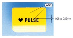
Sansyu's milling process reportedly can hold feature tolerances to ±2 to 5 microns when cutting steel. The tooling has been used to produce a two-color 0.25-mm-thick part with 0.02-mm-wide letters molded in (see photo on p. 39). Sansyu has also cut molds for gears having 24 teeth and a 2.6-mm O.D., as well as a bobbin measuring 1.11 x 0.96 x 0.64 mm.
Deposition methods emerge
A brand-new approach to micro-tool making is a uv-lithography technology previously used in the semiconductor industry. This so-called LIGA process creates a positive model of the part using uv lithography. The model is then electroplated to form the tool cavity. The LIGA process was developed for micro tooling by Mimotec, which reportedly has five or six micro-molding customers in North America. "We have more than 2000 micro molds in commercial production globally, producing nearly 1 billion parts per year," declares Robin Francois, North American sales manager at Swiss Agents LLC, which represents Mimotec.
The process starts with a base, or "wafer," of glass or silicon, onto which a layer of photo-curable epoxy is applied. Next, a thin, chrome-coated mask is positioned atop the epoxy. The mask is cut out in spaces to expose the epoxy underneath. UV light is beamed onto the mask and hardens the exposed epoxy to a depth of about 0.020 in. The first mask can be replaced by another mask to expose another 0.020-in. feature. The total height of the features can be 0.060 in. The hardened epoxy is electroplated with nickel or a nickel alloy, and then the epoxy is dissolved away, leaving a core or cavity. The resulting component has a surface finish that is much smoother than can be produced by EDM, milling, or chemical etching, claims Francois.
The LIGA process allows production of free-form features spaced just 10 microns apart. This compares with minimum spacing of about 100 microns when using EDM or milling, says Francois. Part dimensions reportedly are as accurate as ±2 microns. The process also allows production of multiple or family molds on one wafer. "The costs of LIGA are the same whether making one cavity or eight," says Francois. LIGA can produce a mold component in six to eight weeks, and the component can last as long as steel tooling. According to Francois, "some customers have run up to 5 million cycles per cavity insert."
The technology does have a few limitations. First, making the initial mask is expensive, but the mask can produce numerous molds. Second, LIGA can shape the x and y axis of a mold in any desirable way; however, the vertical axis must always be a straight wall, as the light source from above cures the epoxy.
The Center for Manufacturing Innovation at Fraunhofer USA is cooperating with the Dept. of Manufacturing Engineering at Boston University in developing a system that combines lithographic machining strategies and ultra-precision milling into a single technique. The goal is to produce fully assembled, three-dimensional micro-tooling systems that can incorporate metallic and polymeric materials and span a size range from microns to millimeters.
Ultraprecision Manufacturing of Self Assembled Micro Systems (UPSAMS) is a deposition technology that creates a sacrificial layer and a structural layer, both of which are milled to produce a part or cavity. UPSAMS starts with a sacrificial material that is deposited by an electrolytic process onto a plate or base to form a block. The sacrificial material can be epoxy or copper, for example. A cavity or negative form of the desired tool shape is milled into the sacrificial material, using an ultra-precision milling tool such as one with a diamond edge.
A thick layer of structural material, such as nickel or a nickel alloy, is then electrolytically applied over the sacrificial layer. The structural material, which covers the entire top surface of the sacrificial material, fills in the negative form milled into the surface. Most of the structural material is then milled away down to the level of the sacrificial layer, except for a positive form of the upper surface of the component being made (which can project above the sacrificial layer). The 3D component is then released from the sacrificial material. The result is what Fraunhofer IPT engineer Axel Bilsing, describes as "a micro structure that, to the best of our knowledge, could not be fabricated using any process other than UPSAMS or perhaps layered rapid prototyping processes."
UPSAMS allows construction of true 3D shapes, something a lithography process such as LIGA reportedly cannot achieve. UPSAMS also provides smooth surfaces, which milling alone has trouble achieving. Fraunhofer has used nickel and copper combinations, with the copper as the sacrificial layer. The process has also been tried with a two-part epoxy and a sacrificial copper. Other combinations include aluminum/copper and ceramic/ metal. A limitation of the process is that the diameter of the cutting tool limits the sizes of the component features being molded.
Laser ablation advances
Dr. Arnold Gillner, head of the Micro-Technology Dept. at Fraunhofer's Institute for Laser Technology, says laser ablation can be a fast and effective means of micro-machining. "Lasers have been used for tooling for five or six years, initially on larger tools. But it was not cost-effective. Since then there has been a shift to smaller tooling applications, and there are some positive results," says Gillner. He says the Institute is working with companies to manufacture tooling for injection molds. "We now have four to five partners developing the technology, each with three to five mold projects."
Laser ablation is a pulsed process, where the beam is turned on for 10 to 100 nanoseconds. Longer pulses lengthen the thermal exposure of the work piece, which could reduce final surface quality. The ablation process can use a near-infrared laser that delivers a beam diameter down to 5 microns or a uv laser that generates a much narrower beam—down to 355 nm. Newer diode-pumped lasers with enhanced beam power and beam quality may help to deliver better surface quality and smaller feature geometries. Accuracy of the laser is about ±1 micron, while feature sizes can be as small as 10 microns.
The laser can ablate even very hard materials such as tungsten carbide and leave a finished part with good surface quality, Gillner claims. Lasers can be used to shape any metal, as well as refractive or nonconductive materials, a benefit Gillner cites for lasers over deposition technologies or EDM. However, the cost of a laser—typically about $250,000 for a conventional Yag NIR laser—is far higher than for other types of equipment.


Related Content

50 Years of Headlines … Almost
I was lucky to get an early look at many of the past half-century’s exciting developments in plastics. Here’s a selection.
Read More
Word Games: What’s a ‘Hybrid’?
Any molder will tell you there’s a difference in working with electric vs. hydraulic drives. Servohydraulic is still hydraulic; a hybrid machine is something different. Imprecise use of terms causes needless confusion.
Read More
Fakuma 2023: Wittmann Battenfeld Expands All-Electric Line, Direct-Current Capabilities
Wittmann Battenfeld will introduce the new EcoPower B8X injection molding machine line and show direct current as an energy source for a concept machine that will power its own robot.
Read More
Consistent Shots for Consistent Shots
An integral supplier in the effort to fast-track COVID-19 vaccine deployment, Retractable Technologies turned to Arburg and its PressurePilot technology to help deliver more than 500 million syringes during the pandemic.
Read MoreRead Next

Micromolding Sizing Up the Challenges
Molding multiple parts from one pellet's worth of plastic is a challenge that growing numbers of molders want to tackle. It is driving development of new technology in injection machines, tooling, parts handling, and inspection.
Read More
Processor Turns to AI to Help Keep Machines Humming
At captive processor McConkey, a new generation of artificial intelligence models, highlighted by ChatGPT, is helping it wade through the shortage of skilled labor and keep its production lines churning out good parts.
Read More
Why (and What) You Need to Dry
Other than polyolefins, almost every other polymer exhibits some level of polarity and therefore can absorb a certain amount of moisture from the atmosphere. Here’s a look at some of these materials, and what needs to be done to dry them.
Read More