
More Effective Camshaft Machining
A leading manufacturer of high-performance valve train components installed a twin spindle/twin-turret lathe to bring camshaft machining work in-house. Here, the company explains how it has become more effective using its multifunction lathe to produce small batches of custom racing camshafts.
.jpg;width=70;height=70;mode=crop;format=webp)
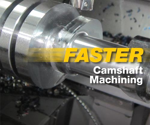
Bringing twin-spindle/twin turret lathe technology in-house...
...enables Comp Cams to produce billet racing camshafts much quicker than when it outsourced camshaft machining.
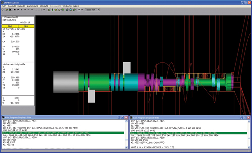
Machining simulation is performed after a program is created for a new camshaft design. After that, a dry run is performed on the lathe followed by a test part created from low-cost mild steel. Once the process is verified, production can ensue in the specified material.
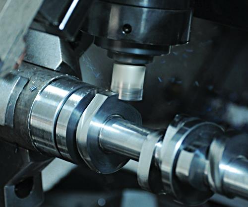
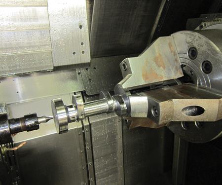
Camshaft core machining begins with a bar clamped in the main spindle that extends out a few inches.
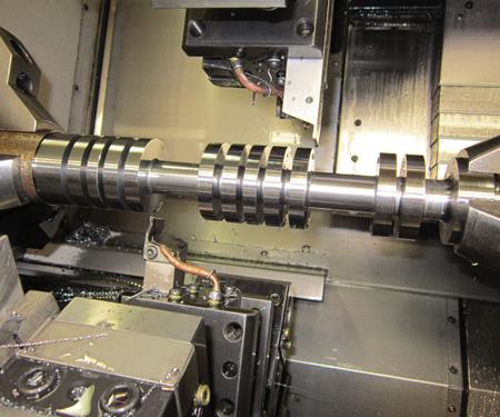
The lathe then turns and mills features into the front face of the camshaft. Next, the sub-spindle pulls the bar out for grooving...
...and lobe milling on a 10-inch section.
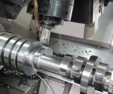
Once that section is completed, the sub-spindle consumes the machined section and pulls the bar out further to repeats those operations on the back section of bar.
Finally, the sub-spindle consumes nearly the entire bar for turning and milling work on the back face of the camshaft.
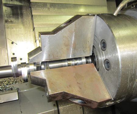
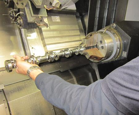
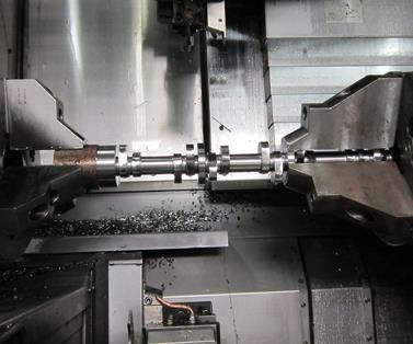
Longer 6-inch jaws on the sub-spindle enable it to clamp at least two journals of every camshaft Comp Cams manufactures.
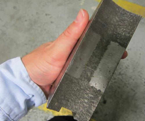
A tungsten-alloy coating on the jaws prevents bar slippage during machining.
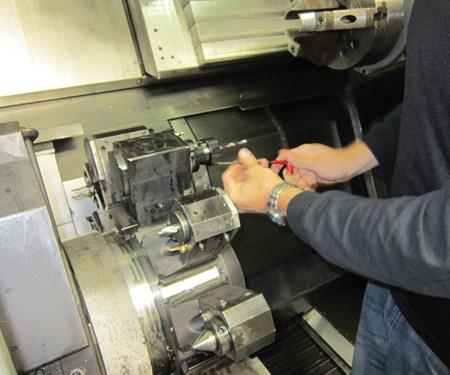
Quick-change tooling on a live-tooling station saves time during production my eliminating the need to touch-off tools each time they are installed.
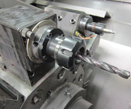
Touch-off for all tools used in that station only needs to be performed during setup.
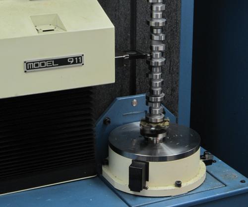
This Adcole cylindrical coordinate measuring machine orients camshafts vertically for measurement results that require no need for sag correction. It takes less than a minute for an operator to enter camshaft feature specifications to measure.
Share
Read Next
When I first spoke to Billy Godbold, he was at a track watching a professional drag racing team test a custom camshaft. Mr. Godbold is the engineering group leader for Comp Cams, the valve train component manufacturer that supplied the camshaft. One month earlier, Comp Cams’ design group had just started contemplating camshaft materials and geometries for this application. Moving from design to completed billet camshaft so quickly would not have been possible years ago when the company outsourced the machining of its high-end racing camshafts.
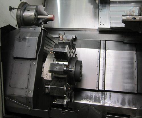
Today, Comp Cams machines small batches of racing camshaft cores on a twin-spindle/twin-turret lathe from Okuma. (Camshaft cores are camshafts that have their primary features machined, but still require subsequent heat treating and grinding operations.) Bringing this machining capability in-house enabled the company to greatly speed turnaround of custom camshafts for professional racing applications because it no longer had to wait weeks or months to receive camshaft cores. It can now manufacture as many as 12 M4 powder-metal tool-steel camshaft cores in a single eight-hour shift.


Mr. Godbold explains that Comp Cams’ traditional expertise was in grinding camshafts, not machining them. So when the decision was made to install the seven-axis multifunction lathe in 2008, the company relied heavily on the expertise and advice of its equipment suppliers to establish an effective machining process. Comp Cams continues to tap those resources today as it strives to minimize cycle times for camshaft cores.
Luckily for me, “you can’t sell if you don’t tell” is the motto of Paul “Scooter” Brothers, one of Comp Cams’ owners as well as chairman of the board for the Specialty Equipment Market Association. In keeping with the spirit of that saying, company representatives weren’t shy about detailing how they’ve become better at using the advanced lathe during my visit to their Memphis, Tennessee facility.
Succeeding at Speed
The camshaft portion of Comp Cams’ product line is evenly divided into three segments: high-performance/non-racing applications; hobbyist racers; and engine builders for NASCAR, NHRA and other professional race teams. The custom billet camshafts machined in the company’s Memphis facility are used by the professional race teams.
Originally, the prolonged camshaft-core delivery times had the company considering adding a “conventional” cell to produce the small batches that race teams required. Such cells typically include a saw to cut barstock to length; lathes to face the front and rear of the camshaft, add centers and groove the lobe layout; mills to machine details in the front and rear camshaft faces; and additional mills to machine the lobe profiles. Most of these operations required multiple time-consuming setups, too.
The company ultimately decided to go a different route after Mr. Godbold met with Larry Schwartz, who at that time was Okuma America’s president (he’s now the machine tool builder’s chief strategy officer). The men discussed alternate ways to manufacture camshaft cores that would minimize change-overs and simplify setups for production runs of 20 or so pieces. Mr. Schwartz’s idea was to use a twin-spindle/twin-turret lathe. Keeping a bar either clamped between the spindles and/or partially inside of them would enable complete machining of camshaft cores in one setup. Plus, the twin spindles could perform some operations simultaneously.
The company selected an Okuma LT300-MY. Mr. Godbold says that in many ways, the initial concept and programming execution were greater hurdles than the slight machine modifications that were needed for this application. The primary mechanical change to the machine was increasing the size of the sleeves in the main and subspindles so a 70-mm-journal camshaft could pass through them. The company reasoned that because the machine offered a great deal of rigidity and each of its spindles provided 30 horsepower, the lathe would have no problem machining the tough M4 powder-metal tool steels (rated at 30 HRc) common to its billet racing camshafts.
Prior to the lathe’s delivery, Comp Cams sent what it thought was a very difficult camshaft core to Okuma’s facility for machine prove-out: a 70-mm-diamter NHRA Pro Stock camshaft with nine journals. Kevin Kraieski, an applications engineer for Okuma, created the initial part programs and machined the first sample parts. Mr. Kraieski set up the part program using multiple variable-style sub-routines for commonly required operations, such as grooving between lobes, milling lobe profiles, drilling and tapping bolt hole patterns, and more. This made it possible for Comp Cams to easily reprogram the complex machine for any number of camshaft designs without starting from scratch each time.
Improving finish in the grooves between the lobes and increasing lobe machining speed proved to be challenging during testing. However, Tim Whitmore, an OEM project manager for Iscar, work closely with Mr. Kraieski to iron out the tooling issues. By the time the machine was delivered to Comp Cams, it could complete a M4 camshaft core in 75 minutes.
The photos on the following page show how camshaft cores are produced on the lathe. An operator manually slides a pre-cut bar into the main spindle, pulls the bar out a few inches to a stop, and clamps it. The lathe then turns and mills features into what will become the front face of the cam. Next, the subspindle moves into position, grabs the machined face and pulls out the bar approximately 10 inches. Grooving and lobe milling are completed on that segment of the bar. Once machining on that section is completed, the subspindle clamps onto some of the newly machined journals and pulls the bar farther out of the main spindle to enable grooving and lobe milling of the back half of the camshaft. (Performing these operations in two small sections minimizes the risk of deflection, vibration and chatter.) Finally, the subspindle consumes nearly the entire bar to enable turning and milling work on the back face of the camshaft.
Comp Cams has refined this process to the point that it can now machine camshaft cores in 35 to 45 minutes. That said, the company had to overcome some initial machining hurdles in order to achieve these faster cycle times.
Early Challenges
As it turned out, the “really difficult” camshaft Comp Cams sent to Okuma for testing proved easier to machine than its other camshaft models. That’s because the camshaft’s nine journals provided more clamping points for the subspindle than a typical five-journal camshaft. Consequently, the original subspindle jaws were not long enough to clamp across at least two journals on the five-journal models (this was necessary to ensure adequate support during machining). Installing lengthier 6-inch jaws enabled the subspindle to clamp across two or more journals on any type of camshaft the company manufactures. The main spindle always clamps solid barstock, so longer jaws are not necessary for that spindle.
Workpiece slippage inside the jaws also proved to be problematic at times because some camshaft materials are more difficult to clamp tightly than others. The solution was applying a tungsten-alloy coating from Carbonite Metal Coatings on the gripping surface of the jaws. This particular coating is applied via electrofusion, which creates a metallurgical bond that is said to be stronger than spray-on coatings. The coating has virtually eliminated linear and angular workpiece slippage from occurring during machining.
Another early challenge was getting used to P codes, which are used to synchronize the motion of the two turrets. P codes not only ensure that the turrets don’t interfere with each other when performing separate operations, but also can signal them to perform identical operations simultaneously. For example, if a programmer wants to face a part with the upper turret and then drill the end of it with the lower turret, those operations have to be synchronized because they obviously can’t be performed at the same time. If the programmer assigns a P10 value to the upper turret and a higher P20 to the lower turret, the upper turret will continue all of its necessary motions until it encounters a higher P value in the program code. If the next P code it encounters is higher than the P code assigned to the lower turret, the upper turret will wait until lower turret is done. However, if the same P code is applied to both turrets, they will work simultaneously.
Unless a camshaft has an odd number of grooves, the lathe performs turning and grooving operations using both turrets simultaneously when the bar is held between spindles. Because the upper turret is optimized to run close to the main spindle and the lower one is set up to run close to the subspindle, the company does not perform pinch turning. However, Mr. Godbold estimates that simultaneous cutting enables the lathe to remove material 30 percent faster primarily because the tool pressure is balanced. In addition, starting the grooving operations at the middle of each section of bar and moving out toward the spindles leaves more stock at either end of the bar section. This ensures rigid support to prevent chatter and also eliminates flexing at weak areas of the bar, which could possibly pinch or break a grooving tool.
Benefitting from Standardizing
Each turret on the LT-300MY has 12 tool stations. Daniel Freeman, the R&D technician for Comp Cams who commonly programs and helps run the lathe, says the company takes full advantage of those 24 total stations. Approximately two-thirds of them rarely change. In addition, tools in several stations are mirrored on both the upper and lower turrets to facilitate the simultaneous machining operations.
Each turret has three different grooving tools. Two of those perform roughing operations. The wider of the two is used as often as possible, while the thinner one is used only when space is tight. The third grooving tool is used for finishing, leaving behind a quality, burr-free surface finish while holding dimensional tolerances of less than 0.010-inch on all linear dimensions along a 24-inch-long camshaft.
The upper turret has two vertically oriented end mills of different diameters that remain in their respective live stations. These are used in conjunction with the machine’s Y-axis movement to perform lobe milling. The narrower 0.75-inch end mill has one less insert than the 1-inch end mill, so the feed rate has to be reduced when that tool is used. Tools in the upper turret’s five horizontal live stations often don’t change either. These perform drilling, tapping, reaming and other operations on the front face of a camshaft.
The lower turret contains center drills used for both the front and rear camshaft faces. This turret also has live horizontal stations set up to create features such as vent holes. Two stations contain miscellaneous tools. These include a multifunction drilling/boring tool that is typically used to create counterbores, and a large indexable-insert drill that machines bores on the rear of a camshaft.
The company uses Exsys/Eppinger Preci-Flex ER32 quick-change adaptors for some of its live-tooling work. Each adaptor can accommodate a drill, tap or mill for use in that single station. During setup, each tool is separately installed in the adaptor and touched off. During a production run, a program stop pauses the machine and prompts the operator to change the tool in the adaptor station to the next tool needed. The operator can change the tool in less than one minute, and touch-off isn’t necessary because the offset for each tool was determined during setup. Mr. Freeman says tools in the adaptor extend out a couple inches farther than normal, but this does not present any clearance issues.
The company has also standardized on coolant, using the same Castrol Syntilo 9918 synthetic coolant for machining that it does for grinding. Mr. Godbold says the company could save money by using a lower-cost coolant, but it appreciates the consistent performance the advanced coolant offers. Comp Cams plans to install an 8,000-gallon central coolant system with a single main paper filter system to supply both the machining and grinding areas in the facility.
One advantage of standardization is that it minimizes the number of tools that must be touched-off for a new job. Typically, an operator has to install and touch-off only a few drills, reamers and taps during setup for a new job. Tool standardization also enables programmers to quickly and easily determine whether additional tooling is needed for a new project. Ultimately, standardization has enabled Comp Cams to reduce change-over times for most new jobs from an entire day to just a few hours.
With that said, the company continues to work closely with Rex Luxmore, its Iscar tooling representative, who Mr. Freeman says is proactive about keeping him up to date with new tooling developments. For example, Mr. Luxmore’s recommendation of grooving tools with a new coating resulted in a 30- to 50-percent improvement in tool life. This assistance is critical, Mr. Freeman notes, largely because of the challenging materials such as M4 powder-metal tool steel that the company frequently machines. This tool steel is not only very unforgiving, but it will work-harden quickly if cut too slowly or lightly.
A Bit of Advice
Comp Cams’s goal is to be a leading developer of innovative valve train components, Mr. Godbold explains. Machining is viewed as a means to that end. Mr. Godbold says companies with a similar approach are well-served to recognize their manufacturing limitations, especially when considering the addition of a complex lathe like the LT-300MY. It’s best to devote some time to learning the ins and outs of such a machine before depending on it for production, he notes.
Scooter Brothers certainly understood that when the twin-spindle/twin-turret machine was delivered. As long as long as the company became more effective using the lathe during the first few months and was able to achieve a half-throttle-level of production within a year, Mr. Brothers was not going to be discouraged.
Mr. Godbold believes this approach made all the difference in the world. He humbly says that Comp Cams proves that a shop with only conventional turning and milling experience can successfully integrate a complex multifunction machine without necessarily being outstanding at machining or programming. However, this requires establishing solid relationships with equipment suppliers that are willing to help a shop achieve its goals. Finding trusted people to work with means everything, he says.


Related Content

SPE Automotive Awards Applaud ‘Firsts’ and Emerging Technologies
The 51st annual SPE Automotive Innovation awards gave nods to several ‘firsts’ and added alternative vehicle systems category.
Read More
PEEK for Monolayer E-Motor Magnet Wire Insulation
Solvay’s KetaSpire KT-857 PEEK extrusion compound eliminates adhesion and sustainability constraints of conventional PEEK or enamel insulation processes.
Read More
New Technology Bonds Aluminum With Polyamides
With many benefits for numerous potential applications, including in the burgeoning electric vehicle market, Celanese’s Zytel Bonding Technology achieves stronger bonds than overmolding or welding.
Read More
Plastic Compounding Market to Outpace Metal & Alloy Market Growth
Study shows the plastic compounding process is being used to boost electrical properties and UV resistance while custom compounding is increasingly being used to achieve high-performance in plastic-based goods.
Read MoreRead Next

Why (and What) You Need to Dry
Other than polyolefins, almost every other polymer exhibits some level of polarity and therefore can absorb a certain amount of moisture from the atmosphere. Here’s a look at some of these materials, and what needs to be done to dry them.
Read More