
Spec’ing a Robot? Match It To Your Press Size & Project
Where is your business today? What might tomorrow’s molding projects look like? These are among the questions you need to answer when deciding what style of robot is best for you.
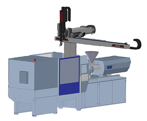
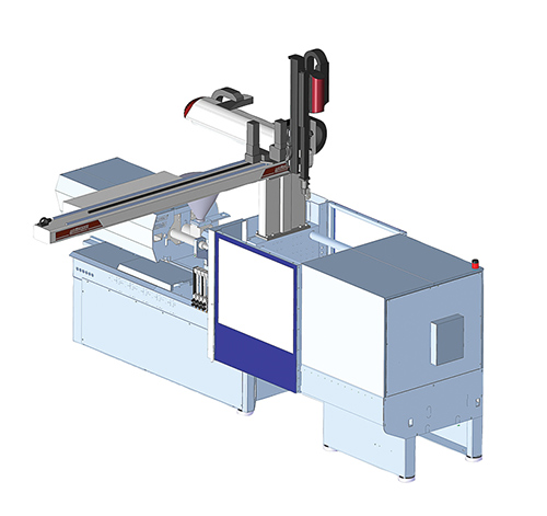

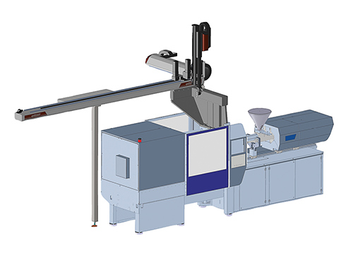
The four standard positions to mount a robot are (top to bottom) operator side, rear side, T-mount, and longitudinal.
Kick-forward designs are more suitable for small- to medium-tonnage presses. They allow the back side of the platen to be clear to avoid obstructions.
For medium to larger molding machines, the kick-back design is more balanced and allows for a heavier payload.


Selecting the proper design for a robot is one of the most critical steps in maximizing its value. If the robot is unprepared for heavier duty, high-payload jobs that arise, it becomes effectively useless. However, to purchase the longest stroke and highest payload available, when the robot will never be handling more than short-reach, light-load tasks, is a waste of your money.
To specify your robot properly, you need to have a thorough and complete knowledge of where your own business stands today, as well as any directions in which it might be going. Be prepared for any potential future, but don’t be unrealistic.


The intention of this article is to help you to use your knowledge of your own molding business to help select the right design for your next perfect robot.
Three main aspects of robot design include:
• Mounting options;
• Payload;
• Kick-forward design (for large-tonnage presses) vs. kick-back design (for small-tonnage presses).
MOUNTING OPTIONS
Every molding cell is unique, and one of the most important requirements of a new robot is that it fit into the design of its cell as seamlessly as possible. Where the robot is mounted on the injection molding machine and where it drops the finished parts are extremely important to creating the most efficient molding process possible. Ideally, the robot will offer traverse-beam modularity, which gives the molder the ability to move it to various orientations to accommodate changes in the workcell.
There are many different positions in which to mount a robot, but the four standard ones are operator side, rear side, T-mount, and longitudinal.
Rear and operator-side part drops are good for applications that require room for an operator or mold setter to access both doors on the press. The rear side of the injection machine can often use shorter horizontal strokes because it requires less access. These are the two most common robot orientations.
The T-mount design is a solution for separating different parts, whether it’s “lefts” on one side and “rights” on the other, or dropping bad parts into a granulator on one side while good parts are moved to the next stage of the molding cell on the other side. This design is also customizable, as the robot can be offset to one side more than the other, allowing it to reach slightly farther in one direction if it has to. Access to the press doors is the same on a T-mount as it is on a normal rear-side or operator-side design.
The longitudinal design, or L-mount, is most useful for molders that need to conserve floor space. By depositing parts at the clamp end of the machine, this design allows molders to fit up to 50% more machines (based on floor layout) than conventional operator-side placement. It also allows use of a central conveyor that will bring all the parts to one central location and require fewer operators. To use this design, ensure there are no obstacles over or past the clamp unit of the press such as clamping cylinders, oil filters, water lines, or light fixtures. The molder should also be sure there is room for beam support legs and that the horizontal stroke can make it past the clamp by at least the width of the tiebars.
Payload Handling
Robots should have sufficient payload for current and future application needs. Remember that payload handling is not just a measure of the plastic parts, or shot size:
Payload = Shot size + EOAT weight +
Center-of-gravity offset allowance.
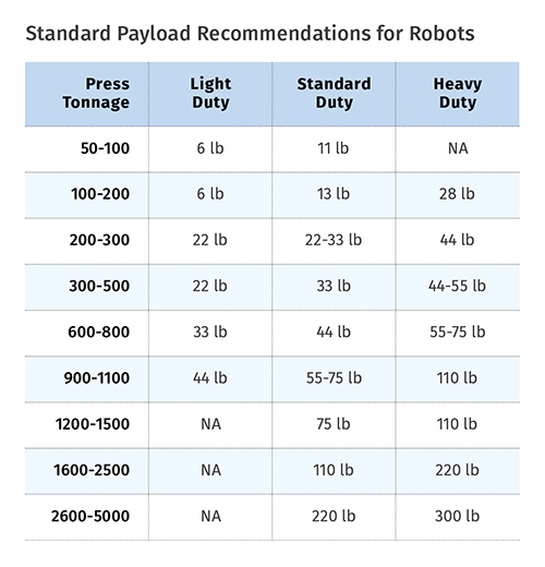
For example, due to its inclusion of heavier materials and sturdier EOAT, an insert application on a 500-ton press might require a 55- to 75-lb robot payload capacity when all payload sizing criteria are calculated—even though the plastic parts themselves weigh only 2 lb. Remember, long-term reliability and robustness are both important considerations when calculating proper payload-handling specifications. See the accompanying table for standard payload recommendations for your robot.
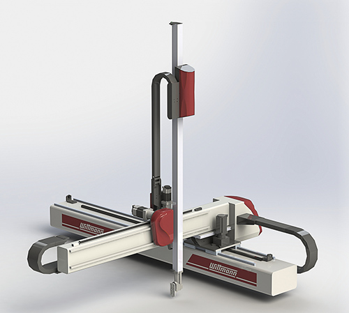
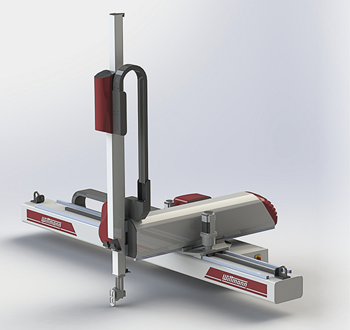
Kick-Forward vs. Kick-Back
Small to medium-sized machines often require a kick-forward, or carriage-forward, design. This design allows the back side of the platen to be clear to avoid obstructions such as a hopper on a short-barreled injection unit, throat-mounted dryers, building columns, catwalks, etc.
Medium to larger machines can benefit from robots with a kick-back, or carriage-back, design, which is more balanced and allows for a heavier payload. This payload, as mentioned earlier, takes into account end-of-arm tools, so this design is also useful when a molder needs an oversized EOAT for the likes of instrument panels, bumper fascias, or house-siding panels. The kick-back also allows clearance for obstructions over the mold, such as core cylinders and unscrewing racks.
Secondary flip or rotation axes can also help to remove parts from larger molding machines. These axes can be pneumatic or servo driven to allow the part to rotate or flip at the same time that the robot is exiting the mold area. This allows the part to be manipulated more easily and more completely to help it fit through difficult spaces while exiting.
Sometimes, with presses of 1500 tons and above, the press height allows no room for a gantry-style robot to be mounted and clear obstructions like overhead cranes. Most robot manufacturers have options for crane interlocks. These interlocks help to ensure that the robot is parked in a safe location before allowing the crane to move over the press.
Another tip: Robots should allow for easy programming in three dimensions simultaneously to permit curve motions, not strictly linear, single–motion-at-a-time programming. 3D motions make the sequence more efficient and reduce wear and tear on the robot’s mechanics.
To achieve this, robot drives must be properly specified. Today, servo drives are generally standard, but there are options within the servo family for high-speed and heavy-duty applications. High speed is required for sub-10-sec cycles and heavy duty is required for applications such as pallets or large automotive parts.
Note that some robot manufacturers still use pneumatic cylinders instead of servo drives. These are inferior in every way, limiting your programming, stunting your payload, and requiring more maintenance than a full-servo option.
Robots also should have options readily available for special requirements such as additional inputs and outputs, an additional access door, box-filling controls, extended line cords, tooling identification, and crane interlocks.
As always, these are general guidelines. Every molder is unique and has differing applications and requirements for its robots. If none of these categories quite fit what your company is after, contact your robot supplier and it can work with you to figure out exactly the right fit for your specific usage.
ABOUT THE AUTHOR: JASON LONG
Jason Long is regional manager, robots and automation, for Wittmann Battenfeld USA, Torrington, Conn. Long started his career at Wittmann Battenfeld in 2007 as a robot field-service technician. Before joining WB he worked for eight years as a lead automation technician for SAS Automation. Contact: (860) 496-9603; jason.long@wittmann-group.com; wittmann-group.com.


Related Content

Cobot Creates 'Cell Manufacturing Dream' for Thermoformer
Kal Plastics deploys Universal Robot trimming cobot for a fraction of the cost and lead time of a CNC machine, cuts trimming time nearly in half and reduces late shipments to under 1% — all while improving employee safety and growth opportunities.
Read More
Drones and Injection Molding Ready for Takeoff
Drones and unmanned aerial vehicles (UAV) are approaching an inflection point where their production volumes — and functionality — will increasingly point to injection molding.
Read More
Five Ways to Increase Productivity for Injection Molders
Faster setups, automation tools and proper training and support can go a long way.
Read More
Ensuring Repeatability: The Key to Effective Injection Molding Automation
One of automation’s key promises is repeatability: the same movement to the same location, time and time again. But to achieve that, all elements involved — robot, machine, EOAT, mold — must be in and stay in alignment.
Read MoreRead Next

Advanced Recycling: Beyond Pyrolysis
Consumer-product brand owners increasingly see advanced chemical recycling as a necessary complement to mechanical recycling if they are to meet ambitious goals for a circular economy in the next decade. Dozens of technology providers are developing new technologies to overcome the limitations of existing pyrolysis methods and to commercialize various alternative approaches to chemical recycling of plastics.
Read More
Understanding Melting in Single-Screw Extruders
You can better visualize the melting process by “flipping” the observation point so that the barrel appears to be turning clockwise around a stationary screw.
Read More
Why (and What) You Need to Dry
Other than polyolefins, almost every other polymer exhibits some level of polarity and therefore can absorb a certain amount of moisture from the atmosphere. Here’s a look at some of these materials, and what needs to be done to dry them.
Read More