
Taking the Temperature of Mold Productivity
Increasing traffic in transfer tooling from molders that have shuttered operations or are unable to successfully produce parts is driving interest in a long-established but under-utilized diagnostic technique for injection molding.
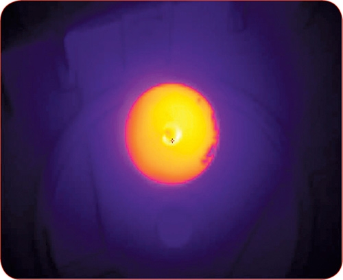
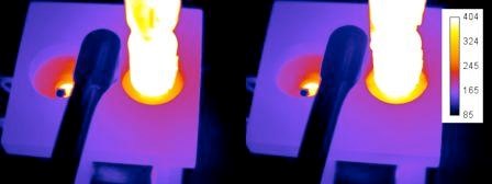
A thermal diagnostic scan of a tool troubleshoots mold issues faster than traditional means. PSG trained an IR camera on a mold cavity, revealing a slight difference in the contact of the nozzle tips as the cause for an imbalance in the manifold.

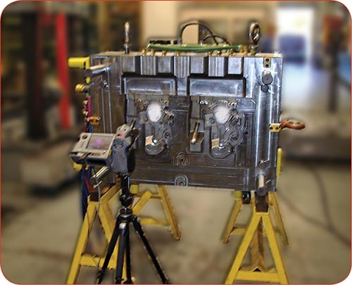
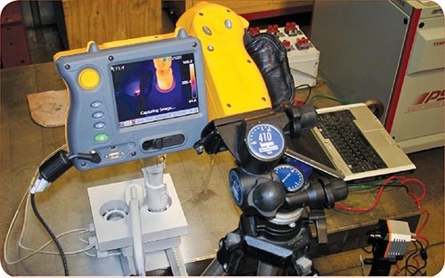
Setup of IR cameras at PSG to test heat losses from hot-runner nozzle adapters to the cavity plate. Thermal image is shown on the back of one camera. A second camera is at lower right, which feeds the image data to a PC. Note white coating on nozzle and mold plate to control IR emissivity. For more on this test, see Sidebar.
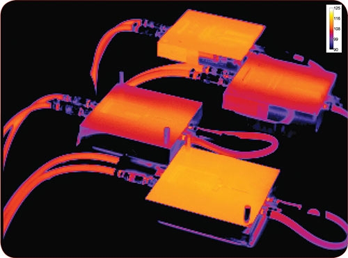
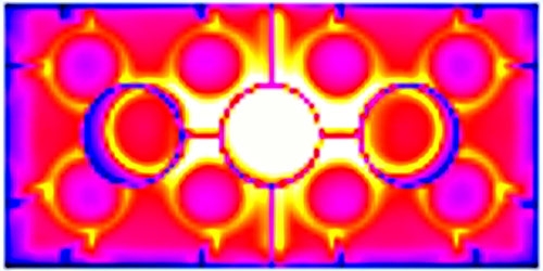
This PSG thermal image shows the uniform heat distribution of aluminum tools (top/bottom) vs. the localized heat isolation in identical steel tools (left/right) under identical water-cooling conditions. This is one reason why aluminum tools are catching on.
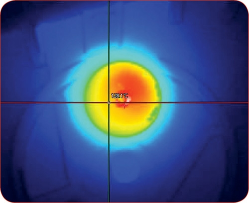
At the K 2010 show, the South German Plastics Center (SKZ) and Wittmann Battenfeld demonstrated the value of thermography for process control. A robot demolded a part and presented it to an IR camera. The thermogram displayed on a laptop showed the part's thermal profile compared with an ideal part. The thermal difference was shown separately, with hot spots in red. SKZ software used these data to automatically adjust water valves on the mold circuits. (See our January K show report for more details.)


Increasing traffic in transfer tooling from molders that have shuttered operations or are unable to successfully produce parts is driving interest in a long-established but under-utilized diagnostic technique for injection molding. Digital thermography is infrared photography and analysis of the surface temperature of a mold or a molded part. One reason for the revival of interest in thermography is that “inherited” transfer tooling often arrives without data on its production and maintenance history, an absence that can cost the next molder valuable time to reverse-engineer, tear down, or “run-and-see” the condition and performance of the tool. “The issue is how to get these tools operating at the highest efficiency in the most cost-effective manner,” says Rich Oles, president and CEO of PSG Plastic Service Group Inc., Stevensville, Mich. (psg-online.us), a hot-runner supplier that has actively promoted thermography since 2004.
Thermography can be used for troubleshooting new molds during construction, process evaluations at the injection molder, or for tooling audits. It can also be used to check parts being molded for online QC, and it can prove useful in other places in the injection process. The technology can give a processor a way to compare an estimated cost of resolving the issue in the tool to the cost of running the tool with the same scrap rates, cycle times and maintenance.


Digital thermography can quickly zero in on the root cause of trouble in a mold by taking a thermal picture of the surface of the tool while it’s in operation with the aid of an infrared (IR) camera. “Taking a thermal view of the surface of the tool or part helps to point your troubleshooting efforts in the right direction,” says Oles. “It can determine what effect the mold, process, and/or resin are having on parts, which can reduce the number of man-hours and technicians required to diagnose and perhaps fix the problem. It can be a factor in lowering scrap generation, trimming cycle time, and reducing the frequency of trips to the tool shop for unscheduled maintenance.”
Thermography can identify issues such poor water connections or blocked flow, perhaps due to scale buildup, through individual mold circuits. The IR camera also can “see” problems arising from mold or hot-runner manifold design, and it can spot a heat imbalance in the nozzle tips. “The two problems that show up most of the time with an inherited tool include a nozzle tip with a bad mold interface, and/or a manifold system that has been assembled incorrectly—i.e., improper wiring,” says Oles.
TOO LONG IGNORED
“Thermography has largely been ignored by North American molders, due mostly to the high cost of the technology as well as the know-how required to interpret the results” says John Bozzelli, founder of Injection Molding Solutions, Midland, Mich. (scientificmolding.com), and a well-known provider of training and consulting services to injection molders. He is also a longtime advocate of thermography.
Just six years ago, molders curious about the technique were put off by the price of a digital IR camera, ranging from around $20,000 to $85,000. The knowledge required to properly set up and evaluate the data from the camera demanded extensive training. “A few molders bought a camera and tried to use it but they got bad readings and then were turned off by the technology,” says Bozzelli.
The aim of thermography is to look for relative temperature differences, so it is ideal for identifying hot or cold spots, but it can be fooled by energy reflected off a shiny surface, which can make the surface appear warmer than it is, says Bozzelli. Another issue is that each material has its own IR signature or wavelength at which it is best read by a camera. It takes some understanding to get it right. Bozzelli says the technology has potential for use on a wide range of mechanical components in injection molding, including the barrel, nozzle, mold cores, cavities, water lines, heat exchangers, dryers, hoppers, and hydraulic lines—or any part that radiates heat.
In plastics, IR technology has been used by thermoformers to measure temperature distribution across the sheet in real time, and to measure temperature of a blown film bubble during extrusion. “If a molder can see the temperature of the cooling lines in a mold increasing, that could indicate the beginning of a problem with your tool, such as the water line is clogging up,” says John Lefeber, v.p. and partner at North Coast Industrial Imaging, Port Huron, Mich. (ncii-online.com), a supplier of IR imaging equipment, software, and services. “A recent study released in Germany stated that more than 30% of injection molds in use there are insufficiently cooled. Sufficient cooling could save the molder $40,000 per tool,” Lefeber adds.
THERMOGRAPHY HEATS UP
At least two factors are contributing to the resurgence of digital thermography. First, IR cameras today are much more affordable, generally priced from $3000 to $12,000. The cameras now also are smaller, which can ease installation, and more functional—able to capture from one frame to dozens of frames of data per second. IR cameras can have software to monitor and record temperatures.
Industry pioneers such as Oles have worked to prove the technology can be useful and easier to implement. Oles has consulted with North Coast Industrial Imaging to narrow the gap between what the camera can do and what the plastics industry needs the technology to do. He has been committed to developing the technology, due to the significant savings it can afford.
“We have seen hundreds of different situations where speedy generation of useful thermography data saves time and money for us and the customer. “If a molder has a 30-drop manifold that takes 12 hours to disassemble, and I can get to the root cause of a problem in two to three hours and pinpoint what needs to be fixed, that is time and money saved,” says Oles.
Bozzelli cites a case in which a molder with a brand-new tool designed to produce a flat panel was experiencing warping. With 16 water lines going in and out of the tool, it would take some time to check each line. “With thermography, you take a picture of the entire mold and can see which areas are hot, which areas are cold, which lines are getting water, which aren’t. You can gain insight into the volume of the cooling media flowing through the channel,” says Bozzelli. When he investigated this molder’s warpage problem, thermography helped to determine the root cause without a lengthy investigation: The gun-drilled lines did not meet up perfectly. Instead of a full-open channel, at one point in the tool there was just a narrow clearance. The molder saved $20,000 to $30,000 in downtime through speedy analysis, said Bozzelli.
Another benefit of the technology is that the user can determine how hot the part can be at demolding yet still retain its final shape. “If you are at the maximum demolding temperature you can shorten the overall molding cycle,” Bozzelli adds. “Thermography helped one molder shave 8 sec off the overall cycle time, trimming it to about 12 sec from 20 sec, a 40% saving. It can be used on complex, valve-gated tools with multiple drops as well as parts with large variation between thick and thin sections.”
Bozzelli notes that thermography has uses in other areas of the molding process. As a demonstration, he took a thermal snapshot of a toggle link of a press that was not making consistent parts. The image showed one link was hotter than the other. The molder had spent three months looking for the source of the problem, spending $150,000 in maintenance. Bozzelli discovered the toggle linkage was not getting lubricated, causing the heating, which resulted in excessive deflection of the platen during injection. Bozzelli also aimed the IR camera at an electric motor that drove the water pump for a chiller on the same press. The molder could see that the winding was burning out. “It saved him $50,000 to know this ahead of time.”
World-class molders are starting to see the light. One already has found success with a complex transfer tool. Custom molder Hoffer Plastics in South Elgin, Ill., implemented thermography with the assistance of PSG and North Coast Imaging, as a diagnostic tool in a demanding automotive application. “We inherited the tool in November 2009 after the previous molder could not keep the tool running to meet production needs,” says Jack Schedd, Hoffer’s v.p. of development.
The mold is a tandem design with two parting lines to produce two different parts. The tandem mold alternates which parting line is closed, allowing injection, pack, hold, and cooling to take place while the other mold is open for part removal. To make the job even more challenging, the part requires a highly heat- and shear-sensitive resin, which put a premium on minimizing material residence time. In addition, the part is lightweighted by 15% via the MuCell microcellular process from Trexel Inc., Woburn, Mass. (trexel.com). The tool is used on a 600-ton press to produce left and right door modules for Ford’s F-150 truck. “This is the only tool making these parts,” says Schedd.
Hoffer needed to find and resolve the issue while minimizing downtime in order to keep production on schedule. The firm spent 90 days applying its extensive in-house tooling knowledge to solving the issue, which included difficulties in controlling the hot-runner system. “If there is any issue with the stop and start of the molding cycle, the material freezes up,” says Schedd. Hoffer monitored a number of temperature zones in an effort to fine-tune the tool. “We were getting better, we were within 5 sec of the optimum molding cycle, but we were not where we wanted to be after adjusting the control points.”
No drawings or CAD data on the design of the inherited tool were available. Hoffer consulted with PSG, which helped Hoffer apply thermography to the mold. “This was the first time PSG had seen this mold and hot-runner system, but within 24 hours we all knew what the core issue was,” Shedd recalls. “The $100,000 hot-runner system installed in the mold wasn’t good. We had to document why this was the cause.” Thermography showed that the hot runner put undue mechanical shear and stress on the material. Eventually, the entire hot-runner system had to be replaced.
Further evidence of the growing interest in thermography was apparent at last fall’s K 2010 fair in Dusseldorf, Germany. SKZ-KFE GmbH, the R&D unit of the South German Plastics Center (SKZ.de), is developing an online thermography system for automatic part-quality checking and closed-loop mold-temperature control. Demonstrated at the booth of Wittmann Battenfeld (wittmann-group.com, U.S. office in Torrington, Conn.), the “Hot Quality Control” system mounted a stationary IR camera on the takeout robot beam The robot presented the part to the camera on each cycle. A PC screen displayed the color-coded temperature distribution of an approved part and of the current shot. The screen also showed any discrepancies in a third image of the part, with areas that were too warm in shades of yellow to red and areas too cold in shades of blue (see photo). What’s more, the SKZ software adjusted the coolant valves on the mold to rectify any imbalances.
IMAGE CONSCIOUS
Thermography can be executed continuously or intermittently, but the main point is to capture the image at the same moment during the process, whether it is at the start of pack/hold or when the part is in the grip of a robot outside the mold. The thermal image of a cycle can be compared with the scan of an ideal part. PSG, which offers thermography as an integral part of its own internal quality control and as a troubleshooting and audit service for customers in North America, takes a thermal profile when the mold is in steady state. “Ideally, there will be Moldflow-type data available to compare with the image,” says Oles. “But if not, we will study the mold design and all available process information in order to predict the likely cause of a problem.” PSG typically positions the camera in a location that allows recording of consistent data in terms of both position and time during the molding process.
It is critical to set up the imaging test in a way that will provide accurate data. Data can be influenced by the person collecting the data, as well as shop conditions. Thermography is a non-contact technology, so ambient air movement can also change the temperature recorded at the surface of the mold. “You have to know how to interpret the color spectrum. The difference between a color shown on the thermal display could be 1° or 300° F,” says Oles.
Using the correct emissivity settings for the camera is also important, or else the camera can give false temperature readings. Another factor is that steel reflects about 80% of IR, especially unpainted, highly polished steel. Painting the mold or coating it with a spray-on powder may be a necessary step to reduce confusing reflections—but care must be taken to avoid any Class A mold surfaces. Warns Oles, “If you don’t coat the mold, you will, in effect, read the thermal profile of all the objects around the mold (including yourself!) and every time you move your vantage point, the thermal profile will appear to have
changed.” Textured plastic parts usually can be thermally scanned without any surface preparation.
To further promote digital thermography, PSG is developing a new technique that makes it simpler for a molder to get an image of the part in the mold, which can then be compared with a flow simulation of the part molded under ideal conditions. Its new “Thermal to 3D” approach will allow molders to automatically generate and overlay graphic files of the tool design with flow-simulation data and the thermography images to spot heating and cooling problems. Explains Oles, “I look at the hot or cold spots. Is there a feature that
isn’t correct and causing the issue? Is it a lifter or the cooling or the temperature at a tip? Or is there a component sticking? You can focus on the area of concern without having to go through every aspect of the tool from top to bottom, which makes for very efficient use of time.” A laptop can receive the data, and software can convert the thermal image into a digital image, which can be 3D.
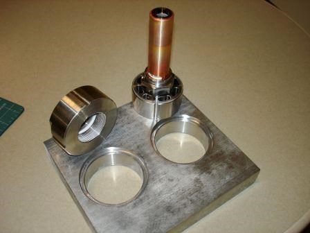
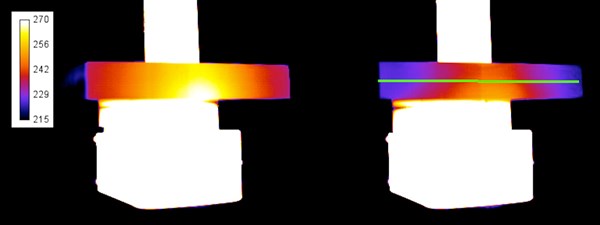
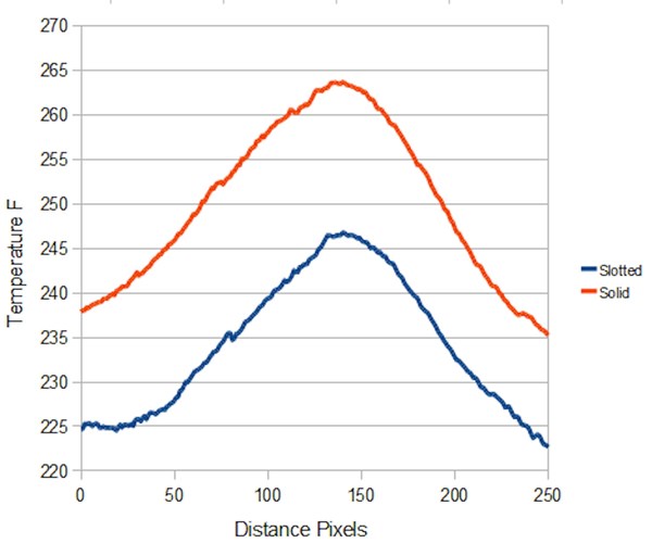
Thermography Case Study: Hot-Runner Nozzle Adapters


Related Content

Inline Inspection System for Wood Plastic Composites
Pixargus’ ProfilControl 7 DX WoodPlasticComposites measure all dimensions and geometrics, including deep grooves.
Read More
Datacolor Acquires Matchmycolor
The acquisition of the specialist in color formulation and communication software further expands Datacolor’s global industry presence in color management.
Read More
Handheld NIR Instrument Distinguishes PET from PETG
Mobile spectroscopy from trinamiX detects more than 30 different plastics—and now PET vs. PETG as an aid to recycling.
Read More
Tracing the History of Polymeric Materials -- Part 30: Polyurethane
In the world of polymers, polyurethane chemistry is probably the most versatile. This a resulted in a wide range of products made from these materials and given the industry the flexibility to respond to the progressive march of regulatory concerns.
Read MoreRead Next

INJECTION MOLDING: Automation and Integration At K Show
There were new presses of all stripes aplenty at K 2010, but the “wow” factor was supplied by automated work cells and integrated manu-facturing systems performing multiple operations before, during, and after molding.
Read More
Troubleshooting Screw and Barrel Wear in Extrusion
Extruder screws and barrels will wear over time. If you are seeing a reduction in specific rate and higher discharge temperatures, wear is the likely culprit.
Read More
How Polymer Melts in Single-Screw Extruders
Understanding how polymer melts in a single-screw extruder could help you optimize your screw design to eliminate defect-causing solid polymer fragments.
Read More