
Tooling: Dealing with Sprue Bushings On the Production Floor
Causes of and solutions to some problems you probably deal with every day.

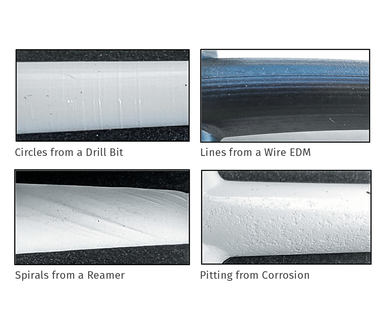
Various causes of bad surface finish in a sprue bushing.
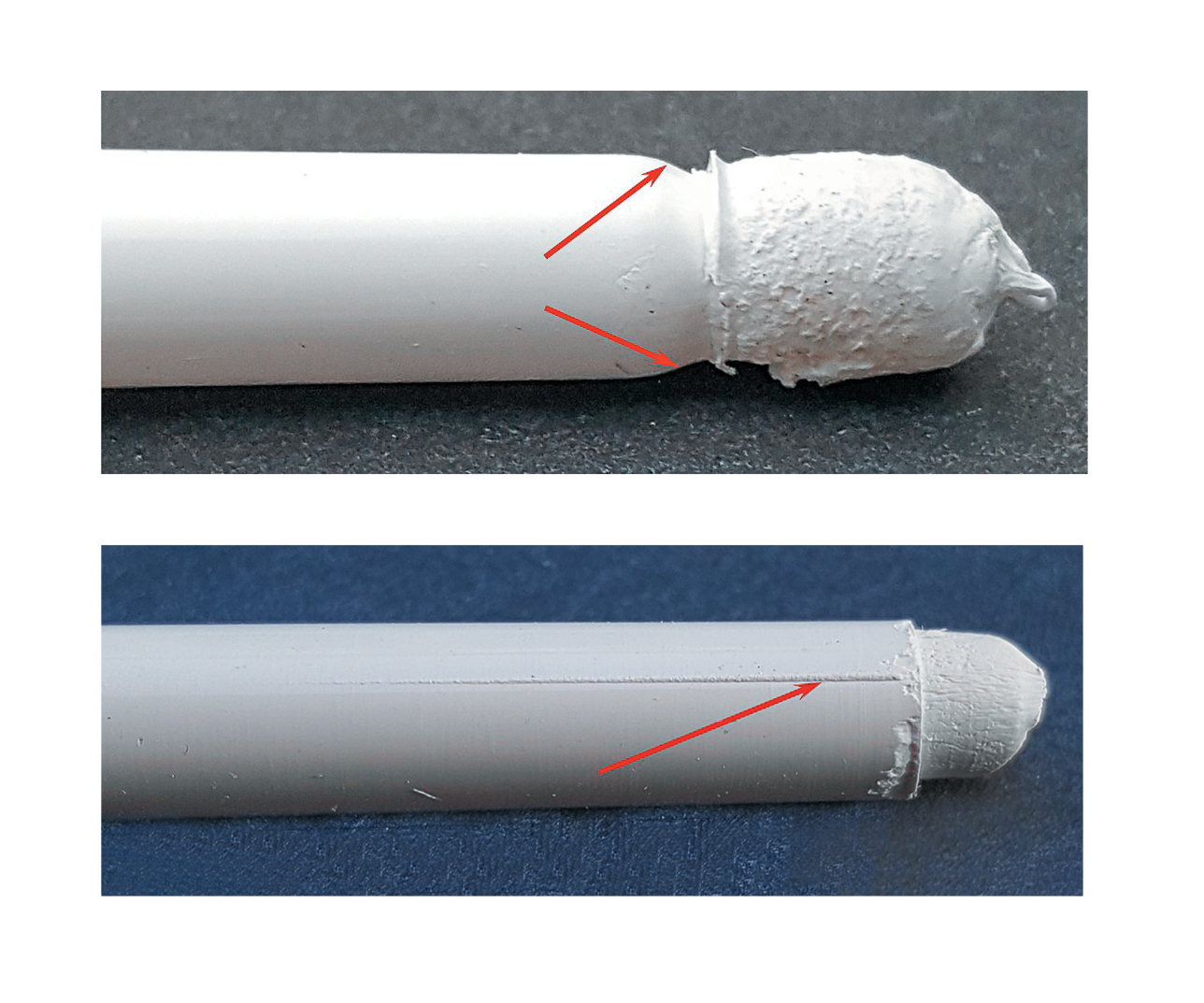
“Necking” (top) on the end of a sprue indicates a hobbed nozzle seat caused by using sprue break. A raised line (bottom) beginning at the orifice of a sprue indicates the bushing might be cracked.
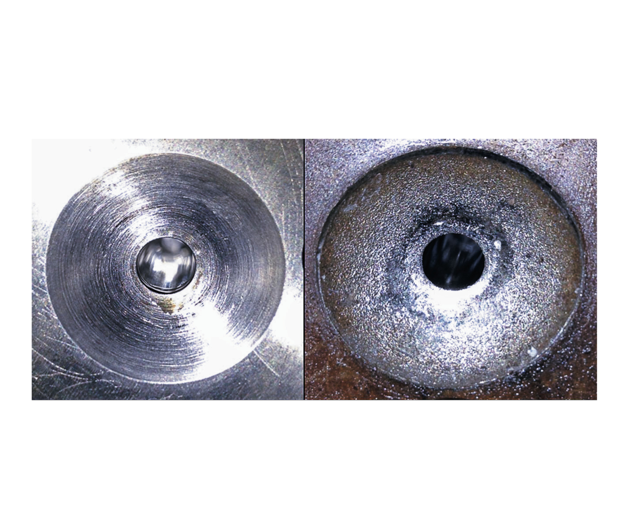
EDM’d nozzle seats (right) provide a better seal with the machine-nozzle tip than those machined with a cutter (left).
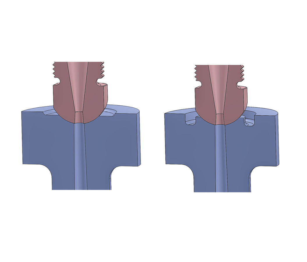
Adding a counter-bore (left) to the face of a sprue bushing can help eliminate cold slugs. Relieving a portion of the sprue-bushing face (right) helps reduce the heat-transmission rate.
In cold-runner molds, the greater the nozzle-seat contact area, the more likely the formation of cold slugs.


In July’s column on sprue bushings we discussed how to reduce the mass of plastic where the sprue, runner, and cold well intersect at the parting line. August’s column discussed additional ways to further improve the cycle time and avoid some processing problems. Both columns focused on the up-front mold design. This month we will focus on identifying and dealing with sprue bushing issues out on the production floor.
Shrinkage: A molded sprue needs to shrink a little to negate its taper lock within the bushing. The amount it shrinks is directly related to the material type and how tightly it is packed out. Unless you’re molding a material with a very low shrinkage factor, such as liquid-crystal polymer (LCP) or an amorphous material that is heavily loaded with filler, obtaining enough shrinkage to release the sprue from the bushing shouldn’t be a problem.


Damage to a sprue bushing often occurs while removing a stuck sprue.
Where you get into trouble is when the molding process overpacks the sprue and prevents it from shrinking. This often happens when the packing pressure continues long after the gates have frozen (see Injection Molding Know How, Nov. ’15, “Gate-Seal Testing Done Right”). It can also become overpacked if the sprue orifice is still molten during a fast screw recovery or when high backpressure is used to mix colorant. Additionally, if the mold’s cooling of the sprue bushing is poor and the cycle time is relatively fast, there may not be enough time for the sprue to shrink.
Surface Finish: Does the bore of the sprue bushing have any pitting, rust, scratches, or machining marks? These conditions can cause a sprue to stick in a bushing. Except for pitting due to corrosive or abrasive materials, all of the other conditions are due to poor maintenance or human error.
One of the most common causes of rolled edges or internal scratches occurs when floor personnel try to remove a sprue that is stuck in a bushing. The usual method is to drive the sprue out from the nozzle seat side with a brass rod. But sometimes it’s difficult
to get a rod into position. That’s when a brass screw is heated with a propane or MAP gas torch and inserted into the sprue from the mold’s parting line.
When the screw has sufficiently cooled, it’s pried out with a pair of brass pliers. These “soft” tools are available from several molding supply companies and are an absolute necessity for production personnel. I often thought it would be a good idea to put the price tag on the outside of every mold. Maybe then, floor personnel would think twice about going near a mold with a hardened-steel screw, screw driver, gate cutter, or pair of pliers.
Nozzle Seat: The sprue-bushing nozzle seat should be inspected at every startup. Look for rolled edges, dents, chips, cracks, burrs, residue buildup, plastic, etc. Also inspect the nozzle seat after a production run, so it can be repaired, if needed, while the mold is available. That’s the difference between being proactive and reactive.
When you use “sprue break,” the carriage backs away from the nozzle seat at the end of screw recovery or cooling time, then slams against the nozzle seat at the start of
the next cycle. Consider this: If the mold has a 20-sec cycle, the machine nozzle tip jack-
hammers into the softer sprue bushing’s nozzle seat 4320 times a day. Using sprue
break can hob a sprue bushing in a very short time. The result is a deformed nozzle seat with
a smaller, bell-mouthed orifice. In order to avoid an undercut condition, you now have to use a smaller machine-nozzle tip orifice, which is not what was originally used to establish the best process. It’s difficult to see this kind of damage in the bushing, but it’s obvious on the molded sprue. Look for a radius at the tip. That’s not caused by the sprue being stretched
out during removal—it’s a hobbed nozzle seat.
A worst-case scenario would be if you see a protruding line beginning at the orifice. That’s an indication the bushing is cracked.
I used to think that the machine-nozzle “touch force” was the root cause of this nozzle-seat hobbing, especially since the larger the molding machine, the higher the nozzle touch force. And some machines have nozzle touch forces as high as 10 tons. But after doing some investigation, I have concluded that the real cause is the kinetic energy of the moving carriage. Mathematically, kinetic energy is equal to one half the weight of the object, times the velocity in which it is moving squared, or KE = 0.5 × m × v2.
Obviously, the larger the injection unit, the more it is going to weigh. But it’s velocity that is the more important factor. Would you rather get hit by a 12-g bullet going 1700 mph or by a 25,000 lb bus moving at 17 miles/hr? Injection carriages that advance and retract via a hydraulic cylinder can travel about twice as fast as those that use servo-driven ballscrews on an electric machine. Therefore, if you have to use sprue break, keep in mind that large hydraulic machines have the tendency to do the most damage. And if the mold was built offshore and the sprue-bushing hardness is questionable, or you’re gating directly into the back of a MUD insert, it would be a good idea to check that you have a tapered reamer and some polishing stones available before you even start.
We all know that sometimes you have to use sprue break to get through a production run. Most machines don’t allow you to control the speed or pressure of the carriage, but they do allow you to set the distance it retracts (usually by a limit switch or timer adjustment). To reduce the potential of hobbing damage, retract the carriage the absolute minimum amount—no more than 1⁄4 in. And don’t forget to inspect the molded sprue at the end of the run, so the bushing can be repaired if needed.
Seat Repair: The most common method of repairing a nozzle seat is with a re-facing tool or carbide cutter, available from many molding supply companies. The radius on these carbide cutters should be checked before using them for the first time. Cutters are not always made within an acceptable tolerance, and the dimension of a sprue-bushing nozzle-seat radius is critical.
I prefer machining sprue-bushing seats by rotary EDM. It costs a little more than using a re-facing tool or ball end mill, but it has some valuable advantages. For example, if the nominal 0.5-in. radius is increased to 0.502 to 0.504 in., there is considerably less chance of leaking molten plastic or carriage blow-back, because the nozzle-tip contact area will be closer to the bushing’s orifice. The stipple finish also makes for a better seal and is excellent at indicating any future damage, or wear from carriage misalignment.
Nozzle Contact: All standard sprue bushings have a nozzle seat machined to a depth of 3/16 or 0.1875 in. This is another example of a standardized component hampering the mold designer’s inclina- tion to design a better mold. Someone probably specified this depth decades ago and no one has questioned it since. In my opinion, having an industry standard 3/16-in. nozzle-seat depth, regardless of the orifice size, makes absolutely no sense at all. Here’s why:
Have you ever established a robust process for a new mold, only to have it go south on the second or third shift? That’s because it can take a considerable amount of time for a mold and all of its component parts to reach thermal equilibrium. The old rules of thumb, such as it takes 28 shots or 60 min for a mold to stabilize, are way too short—24 hr is the new norm. This is particularly true for the junction of a sprue bushing and a machine-nozzle tip, because the rate of heat transfer through the surface contact area is usually pretty slow. By the way, if you don’t use the same machine-nozzle tip on every production run, don’t expect to get the same results. You just added another processing variable into the mix. Everything looks great until the nozzle tip starts to string, or it develops cold slugs and freezes off, long after the first-shift processor went home for the day.
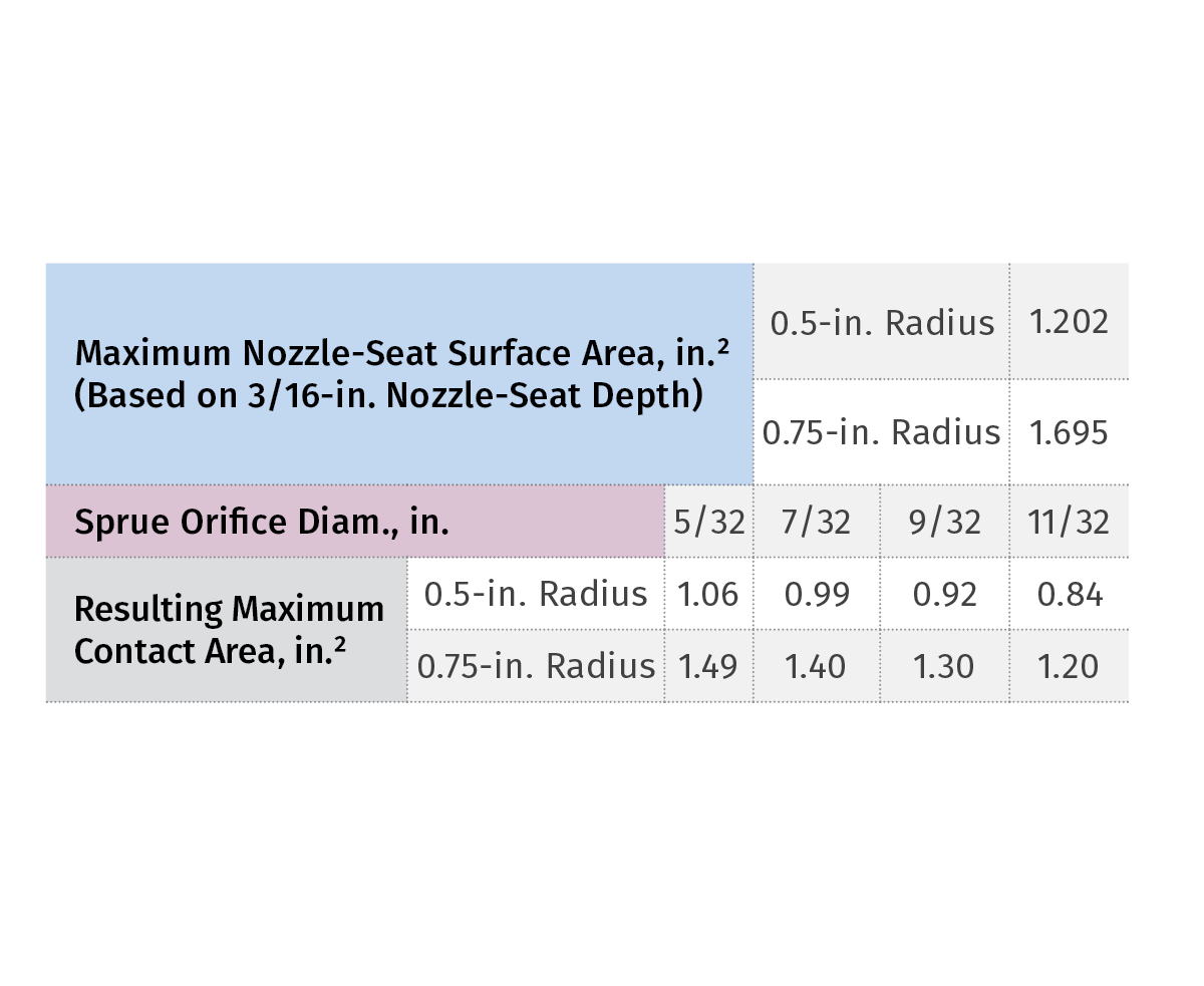
So what does this have to do with the standard 3/16-in. nozzle-seat depth? Everything. A sprue bushing with 0.5-in. radius and a small 5/32-in. orifice has 1.06 in.2 of contact area with the machine-nozzle tip (see accompanying table). The same sprue bushing with a 11/32-in.
orifice has 0.84 in.2 of nozzle contact area—about 20% less. As a result, the bushing with the smaller orifice has larger surface area contact, which leads to considerably more heat being sucked out of the nozzle tip—making it colder and more prone to forming cold slugs. For those of you who use sprue bushings with 3/4-in. radii, your contact area increases by 40% across the board. Note: Every time you repair a nozzle seat, you increase the depth of the seat and the amount of contact area, which further increases the chance of forming cold slugs.
Using sprue break, or increasing the orifice size of the sprue bushing to stop the formation of cold slugs, are really bad ideas. If the root cause is excessive rate of heat loss, the solution is to reduce the rate. Woven Kevlar insulators work extremely well for this purpose. Another method is to reduce the outside diameter of the machine- nozzle tip to reduce the contact area. However, you have no guarantee that this customized tip will be used on subsequent production runs, and reducing the O.D. of a nozzle tip can create a safety hazard.
An alternate, foolproof solution to reducing the contact area is to machine a counter-bore in the face of the bushing. This reduces the heat-transfer rate; and, besides being mold-specific, it will help improve the seal between the nozzle tip and bushing. I suggest starting with a counter-bore depth of 0.05 in. for 5/32-in., 0.035 in. for 7/32-in. and 0.020 in. for 9/32-in. orifices. These depths all result in the same amount of contact area as an 11/32-in. orifice has at the standard 3/16-in. depth.
The yield strength of most steel sprue bushings is about 170,000 psi, or 85 tons/in.2. Therefore, if needed, you can double the depth of these counter-bores without fear of deforming the nozzle seat from excessive carriage pressure—as long as you don’t use the dreaded sprue break.
If you are still fighting cold slugs, even with the sprue bushing counter-bored, try adding a circular channel about 3/16-in. wide by 3/16-in. deep, starting 1/8 in. beyond the nozzle seat. Now it looks and func- tions similar to an insulting support pad for a hot-runner manifold. This will help reduce the rate of heat transmission even more.
ABOUT THE AUTHOR: Jim Fattori is a third-generation injection molder with more than 40 years of molding experience. He is the founder of Injection Mold Consulting LLC, and is also a project engineer for a large, multi-plant molder in New Jersey. Contact jim@injectionmoldconsulting.com; injectionmoldconsulting.com.


Related Content

Back to Basics on Mold Venting (Part 2: Shape, Dimensions, Details)
Here’s how to get the most out of your stationary mold vents.
Read More
The Impact of Hydraulics on Tool Design -- Part 1 of 2
Get a better understanding of their use, proper sizing, and how the tool design and setup in the machine can impact failures in manufacturing.
Read More
How Do You Estimate Cycle Time?
Molders price jobs based on estimated press time, and that is where you can either be very profitable or lose your shirt. But there’s a new, free resource to help you out.
Read More
Why Shoulder Bolts Are Too Important to Ignore (Part 1)
These humble but essential fasteners used in injection molds are known by various names and used for a number of purposes.
Read MoreRead Next

Tooling: Critical Design Considerations for Sprue Bushings
Among them are good cooling, proper orientation, solid retention, structural integrity, generous radii, and an appropriately polished bore.
Read More
Advanced Recycling: Beyond Pyrolysis
Consumer-product brand owners increasingly see advanced chemical recycling as a necessary complement to mechanical recycling if they are to meet ambitious goals for a circular economy in the next decade. Dozens of technology providers are developing new technologies to overcome the limitations of existing pyrolysis methods and to commercialize various alternative approaches to chemical recycling of plastics.
Read More