
Try Multilayer Injection for Efficient Molding of Thick-Walled Lenses
A new approach to multilayer injection molding boosts productivity in making challenging optical plastic parts, such as thick-walled LED lenses for automotive headlights, which have tolerances in the micron range.

LED headlamp of the Mercedes S Class 2013 is produced by three-layer sandwich molding on an Engel duo 600 WP pico combi injection machine. (Photo: Automotive Lighting Reutlingen GmbH).
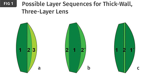
Possible layer sequences for a thick-walled, three-layer lens. Left: Preform 1 one-side overmolded with layers 2 and 3 sequentially. Center: Preform 1 simultaneously overmolded on both sides with layers 2 and 2’ (sandwich variant). Right: Preforms 1 and 1’ connected by injection of a second layer 2 (Figure: Engel)
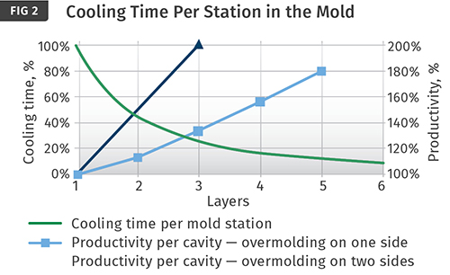
Cooling time per station in the mold, depending on the number of layers as per equation 4 (see sidebar), and productivity as per equations 6 and 7. The respective single-layer part serves as a reference (100%) for comparing the illustrated results for overmolding on one side and on both sides.
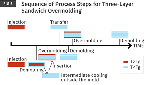
Sequence of the process steps for conventional three-layer sandwich molding (top) and the variant with external intermediate cooling (bottom). The diagram shows schematically how, with external cooling, the different temperature at demolding of the preform (Tg: glass-transition temperature) and the different layer distribution significantly shorten the overall cooling time.
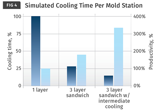
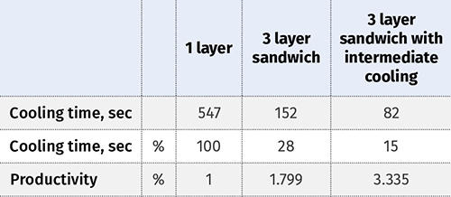
Simulated cooling time per mold station and the calculated productivity (table below) for different manufacturing processes (material: PC). The single-layer part is used as a reference (100%) for comparison.
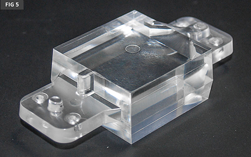
For a process comparison, a cuboidal polycarbonate part (40 × 38 × 20 mm) was used. (Source: Bayer MaterialScience)
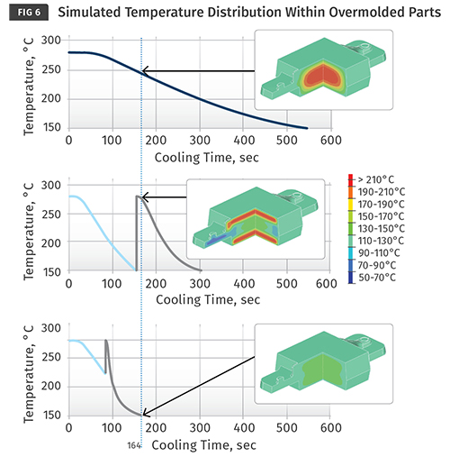
Simulated temperature within the part vs. time for a single-layer process (top), a three-layer sandwich process (center), and the new three-layer sandwich process with external intermediate cooling. (Melt temperature: 280 C; mold temperature for outer layers and single-layer variant: 120 C; mold temperature for inner layers: 70 C). The graphics also include the temperature distribution in the part interior after 164 sec. (Source: Bayer MaterialScience)


In Europe, the main focus of development for plastic optical parts is on thicker lenses for LED lights. Since the cooling time during injection molding increases with the square of the wall thickness, the biggest challenge is to develop economic processes for such lenses. With a typical thickness of 30 mm for automotive headlamps, cycle times of at least 20 min are to be expected with standard injection molding processes.
One possibility for cycle-time reduction is multilayer technology, in which the thick-walled parts are built up from multiple successive layers. The multilayer structure can be generated by overmolding a first layer on either one or both sides, or by subsequently bonding together two previously independent layers by means of an interlayer (Fig.1).


In general, individual layers are all produced on the same injection molding machine. The use of separate injection units for the three layers is already a first step towards short cycle times. This ensures that the process steps of injection, holding pressure, and metering take place simultaneously and independently of one another.
BENEFITS OF MULTILAYER TECHNOLOGY
Approximation formulas for cooling time and molding productivity can be derived from theoretical considerations (see sidebar), and the results can be illustrated according to the number of layers (Fig.2). The technical literature, however, shows that this rule of thumb provides too optimistic results for estimating the cooling time saving with multilayer technology.
Yet multilayer molding offers the possibility of maintaining the mold regions for those surfaces that subsequently have to be overmolded at a lower temperature, since, in an ideal case, the surface quality of the internal layers does not affect the quality of the lens that is produced. If this potential is used for the manufacture of the preform, the estimated cooling-time reduction agrees well with simulated and practical results. For optimizing the layer thickness distribution, it is advisable to carry out simulations.
From Fig. 2, the following statements can be derived:
• For the cooling time per cavity, it is unimportant whether overmolding is performed on one or both sides. In both cases the cooling time is reduced to the same degree as the number of layers increases.
• Overmolding on one side requires a larger number of cavities, and therefore more space in the mold, compared with overmolding on both sides.
• Productivity is a suitable key indicator for an economic comparison, because it includes the assumption of equal numbers of cavities.
• It is only with a large number of layers that overmolding on one side improves productivity to a significant extent. However, the productivity actually obtainable is affected by the times for mold opening, mold closing, mold transfer/rotation, and injection.
• For overmolding a preform on both sides, on the other hand, the productivity increases significantly starting with a three-layer structure.
The sandwich option, consequently, has an advantage over overmolding on one side. This alternative also improves the contour accuracy, since sink marks in the preform due to shrinkage can be compensated by overmolding. Shrinkage of the thinner outer layers is thus responsible for the contour accuracy. This effect is also present for overmolding on one side, but of course only on one side. The quality of the other surface must therefore meet requirements immediately after molding, since it does not contain a corrective top layer. The opening photo shows the three-layer sandwich process in series production of LED headlamps at Automotive Lighting Reutlingen GmbH in Germany.
Despite all the advantages of the sandwich alternative, it must not be overlooked that it requires a more complex mold technology. Retaining the preform in the cavity and transporting it from one cavity to another is challenging, while just a rotary table is sufficient for one-sided overmolding. Also, the simultaneous filling of the outer layers in two-sided overmolding must be well balanced—pressure differences between the top and bottom layers can cause the preform to fracture.
Both overmolding methods can offer a number of benefits. Cold-runner sprues or thin-walled exterior regions limit the possible maximum holding-pressure time. With very thick-walled parts, the sink marks can thus only be counteracted by increasing the holding pressure. This in turn requires machines with relatively high clamping forces. Extreme wall-thickness ratios can, in some cases, only be achieved through multilayer molding. The result is a gain in design freedom.
Along with the cycle time, the residence time of the material in the barrel and hot runner also decreases. That has the benefit of reduced yellowing and therefore greater light transmission. The maximum residence times recommended by the material manufacturers can be maintained.
SHORTER CYCLES FROM LONGER COOLING
It has been explained above, and it can be seen in the sidebar, how multilayer molding can increase the profitability of production of thick-walled parts. It takes advantage of the fact that several thin layers will cool more rapidly than one thick layer. This can increase productivity by approximately a factor of two. However, the resulting cooling times of several minutes are still comparatively long for injection molding.
It is generally assumed that with a three-layer sandwich structure, the preform and the top layers must be cooled to below the glass-transition temperature at the end of the cooling time. However, tests have shown that the preform can be removed much earlier. It must only be ensured that its solidified outer layers are sufficiently strong to withstand the internal pressure and prevent deformation during demolding.
If the preform were immediately overmolded in the next station, no cycle-time reduction would be gained. On the contrary, the still hot inner regions of the preform would be further distanced from the mold wall and the cooling time would be extended.
A new process therefore includes a cooling stage outside the mold between the injection shots. Cooling in air does take longer than in the mold but does not influence the cycle time. Depending on the duration of the external cooling, the
the glass-transition temperature at the end of the cooling time. However, tests have shown that the preform can be removed much earlier. It must only be ensured that its solidified outer layers are sufficiently strong to withstand the internal pressure and prevent deformation during demolding.
If the preform were immediately overmolded in the next station, no cycle-time reduction would be gained. On the contrary, the still hot inner regions of the preform would be further distanced from the mold wall and the cooling time would be extended.
A new process therefore includes a cooling stage outside the mold between the injection shots. Cooling in air does take longer than in the mold but does not influence the cycle time. Depending on the duration of the external cooling, the preform can have a lower average temperature during overmolding than a preform in conventional sandwich technology. As a result, the preform absorbs more heat from the top layers and thereby reduces the cooling time. This effect can be further increased by making the preform thicker and the top layers thinner.
The new process sequence is as follows: A preform for some cycles externally cooled to a predefined temperature is inserted into the mold again and overmolded. A new preform is then produced simultaneously or sequentially—depending on the number of injection units. After the opening of the mold, a finished part and a preform are removed and a preform that has previously been intermediately cooled is inserted again. The removed preform is deposited at a cooling station (Fig.3).
To put a figure on the cycle time reduction gained by cooling outside the mold, Bayer MaterialScience AG, Leverkusen, Germany, performed thermal simulations for a 20-mm-thick cuboidal part of polycarbonate (Fig. 5). Bayer specialists compared a one-layer process, a three-layer sandwich process, and a three-layer sandwich process with external intermediate cooling. The layer-thickness distribution was adapted to the process. In the three-layer sandwich process, the 4-mm-thick top layers required the same cooling time as the preform with 12-mm thickness. In a variant with external intermediate cooling, the preform was assumed to have a thickness of 12.8 mm and the top layers were 3.6 mm.
Figure 6 shows the maximum temperature within the part during the cycle time. Whereas with the one-layer alternative, the highest temperature is always found in the core of the part, the location of the maximum changes for the two multilayer processes.
The criterion for calculating the cooling time of the end part is that all regions of the part must be cooled to below the glass-transition temperature of 150 C. In the alternative with external intermediate cooling, the preform is removed at a time when a 2.4-mm-thick, solidified outer layer has formed, but the core temperature is still 220 C. With this new process, the total cooling time in the mold can be cut in half. Since the number of required cavities is the same as with the known sandwich process, the productivity increases by the same factor by which the cooling time decreases.
The rapid solidification rate of polycarbonate is beneficial for short cycle times. Simulations for acrylic (PMMA) with adjusted melt and mold temperatures generated a total cooling time of 314 sec, or almost twice as long. Figure 6 compares the cycle times and productivity of the three processes for the processing of polycarbonate.
RECORD-BREAKING CYCLE TIME
Tests and simulations demonstrate that, for the manufacture of thick-walled parts with external intermediate cooling, the cooling time in the mold can be reduced by 25% to 50% compared with conventional multilayer molding, depending on the geometry of the part. At the K 2013 show in Düsseldorf, Engel—together with its project partners Bayer MaterialScience and the Krallmann Group (a German moldmaker)—demonstrated the potential of this process live for the first time. An optical lens from PC (Makrolon LED 2245) was molded in record time at the show.
ABOUT THE AUTHORS: Christian Maier M.Sc. is project head in the process technology development department at Engel Austria GmbH, Schwertberg, Austria. Contact: christian.maier@engel.at.
Dipl.-Ing. Josef Giessauf is head of the process technology development department at Engel Austria. Contact: josef.giessauf@engel.at.
Prof. Dr.-Ing. Georg Steinbichler is senior v.p. of development technologies at Engel Austria and director of the Institute of Polymer-Injection Molding Technology and Process Automation at Johannes Kepler University in Linz, Austria. Contact: georg.steinbichler@engel.at


Related Content

Medical Molder, Moldmaker Embraces Continuous Improvement
True to the adjective in its name, Dynamic Group has been characterized by constant change, activity and progress over its nearly five decades as a medical molder and moldmaker.
Read More
How to Extrusion Blow Mold PHA/PLA Blends
You need to pay attention to the inherent characteristics of biopolymers PHA/PLA materials when setting process parameters to realize better and more consistent outcomes.
Read More
How to Optimize Injection Molding of PHA and PHA/PLA Blends
Here are processing guidelines aimed at both getting the PHA resin into the process without degrading it, and reducing residence time at melt temperatures.
Read More
Automotive Awards Highlight ‘Firsts,’ Emerging Technologies
Annual SPE event recognizes sustainability as a major theme.
Read MoreRead Next

People 4.0 – How to Get Buy-In from Your Staff for Industry 4.0 Systems
Implementing a production monitoring system as the foundation of a ‘smart factory’ is about integrating people with new technology as much as it is about integrating machines and computers. Here are tips from a company that has gone through the process.
Read More
Troubleshooting Screw and Barrel Wear in Extrusion
Extruder screws and barrels will wear over time. If you are seeing a reduction in specific rate and higher discharge temperatures, wear is the likely culprit.
Read More