
Unbalanced? No Shortage of Ways to Fix Uneven Filling of Multi-Cavity Molds
The accepted ground rule for balancing melt flow in multi-cavity injection molds is to achieve equal flow distance from the injection point to each cavity.


Non-uniform filling of multi-cavity tools can be addressed with in-mold pressure or temperature sensing, special melt-rotation technologies, valve gates, and improved hot-runner designs. Husky (shown here) also uses computer-aided thermal analysis to design hot-runner manifolds.

iMARC is the newest version of Beaumont’s MeltFlipper technology for overcoming mold imbalances. iMARC introduces the ability to vary the degree of melt rotation with a simple adjustment from the parting line of the mold.

Intellimold control system from MGV Enterprises uses melt-pressure sensing at the nozzle and in the cavity to adjust the injection speed every millisecond—instead of using conventional profile segments—and thereby hold melt pressure within a very narrow range. Ability to correct flow imbalances is demonstrated in this trial with two PP plaques. The thicker plaque on the left filled with only 700 psi injection pressure, while the thinner plaque on the right required 2000 psi to fill. Intellimold could fill both plaques without flashing or overpacking by applying 2000 psi internal melt pressure throughout the cycle, with no spike after the first cavity filled.
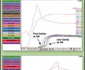
Figures 1 and 2 Curves from RJG’s eDART cavity-pressure monitoring system shows poor balance in a 16-cavity mold (top) because cavities fill at different times. With good balance (bottom) all cavities fill at the same time.

Cavity-pressure control of high-cavitation molds could make for a big wiring problem, but Kistler’s new CoMo injection controller handles up to eight channel signals in a single cable.

Priamus used its Priamus Fill system with cavity-temperature sensing and automatic adjustment of hot-runner nozzle heaters to minimize cavity-to-cavity thickness variances in an optical part.
Mold-Masters’ heater nozzle (left) and Ewikon’s Flow Element Technology (right) are two examples of newer hot-runner components that form smoother, more forgiving turns and angles in the melt channel by milling the channel from two pieces that are joined by brazing. Smoother flow helps avoid imbalances.
Husky’s UltraFlow technology incorporates mixing channels either in the manifold or in the nozzle tip to enhance melt homogeneity without pressure drop.
X-shaped, multilevel hot-runner manifold equalizes flow distances more efficiently than older “H” manifolds, though it does increase mold shut height. (Photo: Thermoplay/Alba Enterprises)
The accepted ground rule for balancing melt flow in multi-cavity injection molds is to achieve equal flow distance from the injection point to each cavity. The sober truth is that even such “naturally balanced” molds can be prone to non-uniform fills, resulting in good parts from some cavities and short shots, flash, or overpacking in others. This is hardly a new problem for injection molders. But there are some signs that it could become more important as simpler molds and molding jobs go overseas and domestic molders take on proportionally more of the complex, multi-cavity applications.
Not all sources interviewed for this article agree on the scope of the problem. “We don’t see a lot of filling imbalances, largely because we avoid varying gate sizes,” say spokesmen for D-M-E Co., a hot-runner supplier. D-M-E starts with a geometrically balanced mold and frequently adds a Moldflow analysis to forestall potential problems. But, as D-M-E sources admit, “There may be only so much you can do, even after the Moldflow analysis. Suppose you move a gate to change the weld-line location—that may raise the chances for a shear imbalance to arise. You may have to change gate sizes to compensate.” However, D-M-E advises against such modifications except as a last resort, because they tend to shrink the process window for the mold.


The majority of sources interviewed agree that unbalanced filling of multi-cavity tools has indeed become a more prominent topic of discussion in recent years. This is due in part to the marketing of a new analysis of the problem and a new tool for combating it. That analysis says uneven filling of supposedly balanced molds is to a large extent inevitable, owing to the basic physics of polymer melt flow. Based on that analysis, the patented “MeltFlipper” of Beaumont Technologies, Inc. (BTI) is a type of mold insert designed to counteract unbalanced temperature, shear, and flow conditions that are actually created by the mold’s runner system.
While a number of industry experts credit BTI with raising awareness of flow imbalances, its solution is hardly the only one available. In fact, there are several. Some are relatively new, but most of have been offered—but perhaps overlooked—for quite some time. These technologies fall into two general categories, “fixed” and “variable.” In the first category are devices placed within the flow path to mix or otherwise manipulate the melt stream. Others are newer designs of hot-runner nozzles and manifolds that are said to minimize shear-induced flow differences.
Other solutions allow adjustment of volume, pressure, temperature, and shear at individual cavities. Some use valve-gate devices to open and close melt channels or provide a variable restriction by partially opening or closing the channel. Another solution is a variable-position mold insert to erase shear variations between cavities. Also available are in-mold temperature and/or pressure sensors to “see” what is occurring in each cavity and feed back a signal to valve gates, nozzle heaters, or the injection ram.
Choosing among these systems depends on molder preferences and technical capabilities: Do you want to put the responsibility in the hands of the moldmaker and hot-runner component supplier? Or do you want the ability to fine-tune the system at each cavity? Perhaps you want to monitor conditions in each cavity as well, and generate electronic records of each shot.
All these different technologies have achieved some level of commercial success, but they also call for different levels of commitment from the molder in terms of capital investment, ease of use, training and maintenance. They also may differ in process sensitivity and responsiveness.
GET CONTROL OF SHEAR
The basic theory of balanced mold filling is to ensure that the melt enters each cavity under the same pressure and temperature conditions. Balanced filling is typically taken to mean that volume in each cavity varies no more than 10% to 20% at 90% fill, according to Bruce Catoen, v.p. of marketing and business development for Mold-Masters.
But no matter what you do to ensure consistent flow lengths, flow-channel diameters, and temperatures throughout the mold, there are fundamental physics principles at work inside the mold that undo all the efforts made at balancing flow to multiple cavities. That’s the philosophy of Dr. John Beaumont, founder of Beaumont Technologies, Inc. (BTI) and inventor of the MeltFlipper. As explained in detail in previous articles (see Learn More box), melt flowing through a runner system develops layers of hotter, more fluid melt near the mold wall and cooler, more viscous melt near the center of the flow channel. This is a result of the melt on periphery of the flow channel experiencing more shear heating from friction with the mold wall. “Due to shear, laminates of melt along the perimeter close to the runner wall can be up to 200° F hotter than the melt in the center of the melt stream,” says Beaumont, “and the viscosity can differ as much as 1000-fold as a result of thermal and shear-thinning effects.”
This laminar structure is split within the runner system and even within the part cavity, with the ultimate result that hotter melt ends up flowing one way and cooler melt the other way, so the melt entering the cavities (or different parts of the cavity) is no longer of the same temperature and viscosity.
These effects can be felt even in single- and two-cavity molds, where melt of different rheology ends up in different regions of each cavity. “That’s why the industry is now looking beyond balance by controlling rheology within the cavity,” notes Beaumont. “Variations in rheology across a cavity can create problem with cosmetics, core shift, warpage, and weld-line strength.”
Beaumont’s MeltFlipper and MAX technologies are mold-design features or inserts placed strategically within the runner system. They rotate the melt’s laminar orientation by a specific amount so that a consistent “slice” of all the hotter and cooler laminates is distributed to each sub-runner. “The melt rotation not only equalizes the distribution of laminates to all cavities, but can strategically position them within each cavity” says David Hoffman, BTI technical director of sales and marketing. This achieves two subsidiary advantages, he explains: “The overall injection pressure is typically governed by the worst-filling cavity, which usually contains the coolest, highest-viscosity melt. Thus, evenly dividing the hotter and cooler laminates among all cavities lowers the overall pressure to fill the mold. Additionally, cycle times are commonly reduced by more than 10% since severe thermal variations and related product dimensional variations are eliminated.”
BTI cites several thousand success stories worldwide with the MeltFlipper. One is Phillips Plastics, a prominent custom molder based in Phillips, Wis. Specializing in precision molding, Phillips used to limit itself to no more than four cavities per tool in order to maintain quality control. But now the firm is regularly running higher cavitation, including 16-cavity tools, successfully with the MeltFlipper, which is making Phillips more competitive in piece price. BTI says another customer is running a 128-cavity tool with the MeltFlipper.
BTI is now taking the technology into thermoset molding, where it reportedly can cut cycle times up to 50% through uniformly distributing the shear laminates and placing them strategically within the part so that the material cures both from the outside in and inside out.
While the MeltFlipper is a fixed device, BTI sees the need for an adjustable melt rotation because resins can vary lot to lot, moisture levels can change, molds can wear unevenly, and some molds run multiple products and in multiple machines. The newest versions are the iMARC inserts, which can change the angle of melt rotation by means of a simple adjustment while the mold is in the press. “This new technology allows the molder to tune the rheological balance to within a few percent without causing any flow restrictions, increased pressure loss, or material hang-ups,” claims Beaumont.
Incoe Corp. supplies MeltFlipper technology in its Opti-Flo hot-runner systems under exclusive global license from BTI. John Blundy, Incoe’s v.p. of business development, says hundreds of Opti-Flo systems have been delivered. They cost about 10% more than a conventional hot-runner system, including BTI’s license fee to use the MeltFlipper technology. However, BTI says this is much less expensive than other melt-balancing technologies, such as the use of in-mold sensors.
SENSOR-BASED TECHNOLOGIES
While BTI takes the approach of attacking the root cause of flow imbalances, most other suppliers accept the fact that small variations in cutting mold steel and changing conditions in the molding shop will always present the possibility of non-uniform filling. These other suppliers offer instead various means of overcoming flow variations, whatever the cause. They focus on the end result—filling all cavities at the same time and pressure—and choose some “handle” on the process to be tweaked to achieve that result.
Cavity pressure sensing and control is one fairly common approach to this goal. “A difference of just a few bars of pressure can have a dramatic impact on part quality from cavity to cavity,” says Mold-Masters’ Catoen.
In an article on diagnosing and fixing flow imbalances in this magazine last December (see Learn More), Mike Groleau, co-owner of RJG Inc., noted that continuously changing imbalances in some hot-runner molds can create frustrating problems that come and go from cycle to cycle, making them very difficult to solve. “The sensor gives molders rich information about the cause of problems, allowing them to solve these problems quicker and easier,” Groleau says. Cavity pressure sensors also confirm part quality automatically, even before the mold opens.
Groleau says molders often don’t associate their inconsistent parts with unbalanced flow in the mold. A way to assess mold imbalance is to deliberately turn off hold pressure to create a short shot. Make sure all parts are at least a little short. Then you can weigh the parts to measure the degree of imbalance.
Once you determine that imbalance exists, Groleau says, cavity pressure sensing may help provide a solution. In some cases, he says, the process can be adjusted to compensate for the imbalance and made more “forgiving” or “robust.” In just a few trial shots, cavity pressure sensing can determine when the first-to-fill cavity is not quite full. Then a low-velocity injection stage can be programmed to occur at that ram position, in order to finish filling all parts with more consistent pressures.
RJG’s eDART cavity-pressure monitoring and control system is designed for multi-cavity applications. Digital sensor technology allows multiple sensors to be connected to the monitor with one cable, allowing easier use on the shop floor.
Another advocate of cavity pressure sensing is Kistler Instrument Corp., whose Swiss parent company reportedly was the first to market this concept in 1975. “The measurement of melt pressure has become increasingly important,” says Oliver Schnerr, head of product management for plastics. “Yesterday’s technology required a separate cable connection to the mold for each sensor, which could mean very involved cabling where multi-cavity molds are concerned.” But Kistler and other firms have come out with new multi-channel technology that allows a single cable to transmit signals from multiple sensors—up to eight in Kistler’s case. The firm recently introduced CoMo Injection, a 24-channel, stand-alone cavity-pressure monitoring system that assesses part quality on a pass/fail basis and controls the injection process in real time (e.g., for switch-over to holding pressure).
Kistler generally advocates placing a sensor in each cavity, though not all customers choose to do so. The benefit of cavity-pressure sensing, according to Kistler, RJG, and other sources is that it not only reveals the end point of filling, but provides a profile of how the pressure develops as filling is completed and packing begins. This allows a more detailed diagnosis of filling or imbalance problems in the mold. According to Schnerr, cavity pressure sensing is most often used for monitoring, diagnosis, and quality control—and to control pressure switchover for the shot as a whole. But in cases of imbalance between multiple cavities, differences in fill time and pressure can be used to correct, either manually or automatically, temperature of hot-runner tips to adjust the balance.
The Intellimold system from MGV Enterprises uses melt-pressure sensing in a different way. Intellimold controls melt pressure within the runner and cavity by means of pressure sensors in two places—in the injection machine nozzle and at the last place to fill in the cavity. The system uses melt-pressure feedback to control injection ram speed continuously and in real time throughout the cycle so as to produce consistent pressure as the melt front advances through the filling cycle. “Combining the two signals into one control signal for the injection machine allows us to monitor and control the machine’s response to the material’s needs every millisecond,” says Milko Gergov, company founder and president. He says this immediate response to the melt behavior is more accurate than conventional injection profiles through fixed linear ramping segments. Incidentally, MGV now offers the Intellimold system with the Kistler CoMo injection process monitor.
According to Gergov, controlling fill in a multi-cavity or family tool requires only one cavity pressure sensor in the last cavity to fill, even when there are severe filling imbalances (see photos). The explanation is that Intellimold maintains constant internal melt pressure (IMP) throughout the filling cycle, even when the cavities don’t all fill at the same rate. If one cavity fills before the others, the Intellimold system will sense the increased resistance to flow after that cavity is full and will reduce the injection velocity instantaneously to prevent melt pressure from spiking, which would flash or overpack the full cavity. That way, all cavities experience the same filling pressure, regardless of whether they fill early or late.
MGV cites the example of a two-cavity mold that was supposed to produce two polycarbonate headlamps weighing 500 g apiece. Without Intellimold, one part weighted 449 g and the other 499 g. “We switched on Intellimold and instantly the part weights were 498 g and 499 g and had less stress and better dimensions because the parts packed out evenly,” says George Feth, director of materials and process development. “Also, the cycle was at least 10% faster.”
Intellimold can produce faster cooling, Gergov claims, because it prevents air being trapped against the tool wall as the melt front advances. Maintaining correct internal melt pressure prevents the frozen skin layers from separating from the tool walls, which would decrease cooling rates by three to five times, says Gergov. “This reduces the need for higher pack pressures to push the skin layers back against the mold, inducing stress in already solid layers.” He says one customer used Intellimold on a 96-cavity PET preform tool. “We trimmed a full second off the cycle and yielded more effectively molded parts.”
“If you look at the top 100 molders in the U.S., cavity-pressure sensing is an established technology,” says RJG’s Groleau. “We have our systems running at eight of the 10 largest molders in North America.” Overall, he says, the technique is used by less than 15% of all the molders in the country but continues to gain acceptance.
Groleau notes a growing number of applications are in higher-cavitation molds. RJG routinely deals with 16 or more cavities. (Kistler says its technology has been used with 96 cavities.) RJG adds that its recent introduction of cavity temperature sensing (see below) will allow even the highest-cavitation molds to be monitored cost-effectively.
Priamus System Technologies has a different approach to solving flow imbalance. Priamus believes that cavity pressure sensing only provides part of the process story. “Post-gate cavity pressure provides the best signal for process optimization,” says president Susan Montgomery, “but it is cavity temperature placed near the end of the flow path that tells us how the plastic is filling the mold and if the material viscosity is changing. With control systems based on melt-front detection, our customers are seeing at least 50% more consistent part weights and dimensions.”
The Priamus Fill system is designed for automatic closed-loop control of multi-cavity and family molds, multi-material injection, sequential valve-gated molds, as well as LSR molds. The Fill system analyzes the filling of each cavity by sensing the melt presence at the end of flow with a cavity temperature sensor and compares the fill-time differences from cavity to cavity. Via communication with the hot-runner temperature controller, Priamus Fill automatically overwrites the nozzle-tip temperatures so that all cavities fill equally at the same time. This means that all of the cavities experience the same holding pressure, which translates to more consistent part weight and dimensions.
Says Montgomery, “This automatic adjustment compensates for material viscosity changes so that more consistent parts are produced” (see graph). Priamus Fill has software interfaces for use with more than 20 hot-runner temperature controller types, and the number is growing. Numerous Priamus Fill systems are running worldwide on molds with up to 128 cavities or more.
The Priamus Fill system includes an option called Priamus Cool, to communicate with the mold temperature controllers and mold cooling circuits. Priamus Cool makes adjustments so that the mold surface temperature gradient is minimized.
The cavity temperature signal can be used for machine transfer from first- to second-stage pressure. This automatic transfer method, as contrasted with “fixed level” type methods (setting a fixed cavity pressure or screw position as the transfer point), also compensates for material viscosity variations. The signal from the cavity temperature sensor is sent immediately (within fractions of a millisecond) as the melt front is detected.
Priamus offers single-cable, multichannel sensor systems and other options for process control. Last year, Priamus introduced the Pass controller, which records cavity pressure, temperature, and—for the first time—real-time online melt-viscosity determination for each cycle. At a glance, molders can see if their process is running within limits and have an immediate indication of part quality.
Typical cavity pressure or temperature monitors and controllers cost from around $5000 to over $10,000. Sensors can cost from $400 to $1100 apiece.
VALVE-GATE SOLUTIONS
Another way to overcome mold imbalance without removing the causes is to use hot-runner valve gates. Ewikon, Mold-Masters, and other hot-runner suppliers say sequential valve gating is an expensive solution to mold imbalance, but it can be used to shut off flow to fast-filling cavities to prevent flashing or overpacking, while allowing slower-filling cavities to continue filling. Peter Rebholz, v.p. of sales at Osco, considers this situation more likely to occur in family molds with parts having different weights and wall sections. “There you anticipate different filling parameters. But if it is multiple cavities of the same part, we rarely see filling imbalances,” he says.
For cases where cavities do not fill uniformly, Osco developed a simpler and less expensive approach than sequential valve gating. Osco’s Flow Control System (FCS) uses a flow-control valve controlled by a worm-gear assembly. The molder can adjust each nozzle’s flow at the press by turning a knob. The setting remains fixed once adjusted. FCS costs more than a standard hot-tip system but less than a sequential valve-gate system.
Varying the flow restriction through pin position in valve gates is also the essential concept behind the Dynamic Feed system from Synventive Molding Solutions. However, this is a real-time, closed-loop flow-control system. “It lets you establish a pressure-versus-time profile for each drop location, letting you determine rate of fill and the level of packing,” says Joe Lang, automotive business manager. Dynamic Feed uses pressure sensors in the mold to control the valve pins in a way that maintains uniform pressure through the filling cycle. “With conventional valve gating or sequential gating, the pressure is typically higher in the center of the manifold, with less pressure present on the outside of the manifold. So the farther the melt flows through the system, the more pressure is lost,” says Lang. Dynamic Feed adjusts the pressures at the nozzle to distribute pressure evenly throughout the flow path.
Dynamic Feed consists of a hot runner, a controller and a hydraulic power source. A Windows-based program is used to set an injection and packing profile for each gate location. The controller reads the pressure at the drop location and matches it to a stored profile by adjusting the position of the flow-control pin using the hydraulic actuator. Each pin is operated independently on a separate real-time closed loop—in effect, permitting independent injection at each gate.
HOT-RUNNER ENHANCEMENTS
Hot-runner suppliers say they have changed the ways they design and manufacture their components and systems to minimize the tendencies for naturally balanced molds to become unbalanced. For example, sources at D-M-E and Mold-Masters note that starting in the mid 1980s, hot-runner suppliers began to design multi-level manifold systems for use with multi-cavity tools, as an alternative to “H” shaped manifolds that placed all of the drops on the same level. Suppliers came up with “X” and “Y” channel layouts having a tiered runner system with one heated channel stacked above the next. These add cost and create a thicker manifold that requires more daylight in the injection press, but they can help equalize flow lengths and allow for higher cavitation.
Mold-Masters also offers a two-piece brazed-plate manifold design that is said to minimize hang-up points and dead spots, which can occur in gun-drilled or pressed-in intersections. “The brazed technology eliminates localized shear heating around sharp corners by eliminating sharp corners like the ones you would see in a gun-drilled radius,” says Catoen. “We have a customer that was using relatively low cavitation and molding the part a little heavier as a safety margin to ensure good fill,” says Catoen. “But he needed to make more units faster or he would lose the job. He changed to a brazed-plate hot-runner system in a stack mold that operated in the same machine as the previous mold. He raised output and was able to reduce part weight by 25% while keeping scrap rates low.”
D-M-E sources acknowledge the advantages of brazed plates for hot runners but also cite disadvantages such as the potential for thermal differences between the plates, which can lead to fatigue.
Mold-Masters and other hot-runner suppliers emphasize the importance of very uniform heat control in hot-runner nozzles to prevent mold imbalances. The nozzle design must ensure consistent and accurate temperature down to the gate area, “so that the thermal gates all break open during the next shot at the same time,” says Catoen.
Independently controlled temperature zones in the manifold are also helpful in overcoming imbalances, say hot-runner suppliers such as Synventive and Melt Design. Synventive uses heat pipes for fast and uniform heat delivery in its Advanced Power Transfer (APT, formerly Kona XP) manifold designs. “Some applications require independent heat control in the gate area,” says Synventive’s Lang. “For these applications, we recommend our Advanced Power Input (API, formerly the MZ line).
Martin Baumann, hot-runner business manager for Husky Injection Molding Systems, says detailed thermal analysis of the manifold at the design stage is an important factor in obtaining good mold balance. Husky models the temperature of the melt-channel wall, not just the surface, by taking into account the plate steel, insulation, water cooling, etc. Baumann says empirical testing of this model shows it can predict temperature within ±2° C.
Ewikon Molding Technology offers a new “Flow Element Technology” designed to minimize flow problems in a multi-cavity hot runner. The technology is used in places where the melt channel splits or undergoes a level change or change in direction. Ewikon’s two-piece design has one half of the channel machined in one block and the other half of the channel in the other. The two blocks are vacuum brazed together to form a plug or block. “This method ensures that the outside and inside angle turns and level changes are perfect, with no extended radius on the outside edge that can led to hang-ups or dead spots,” says president David Boxall. Flow Element Technology is utilized for shear-sensitive materials, quick color changes, and also for unusual situations such as systems with an odd number of drops.
Some hot-runner suppliers apply mixing in the nozzle and/or manifold to ensure thermal homogenization and minimize imbalances. D-M-E sources caution against using static mixers for this purpose, as they can add too much backpressure and provide areas for resin hang-up. Some newer technologies are said to avoid those drawbacks.
Husky, for example, offers its UltraFlow mixing technology, which consists of a spiral melt channel in the nozzle or manifold that mixes the melt. It was designed primarily to reduce molded-in stresses, warpage, and flow lines, as well as to speed color changes. Ultraflow recently became available in Husky’s 750 valve gate.
Melt Design Inc. (MDi) also offers melt mixing in its manifold design. This technology has been applied to two-shot molds, stack molds with up to 2 X 48 cavities, and single-face tools having up to 64 cavities, says president Panos Trakas. He adds, “MDi became aware of the imbalance issues of multi-cavity molds in the early 1990s. We developed a method for balancing and changing melt direction and melt elevations within the manifold, along with very tight control of flow-channel size, and we have had excellent results.”
Technoject, which represents Heitec hot-runner systems from Germany, can help achieve precise balancing of small parts with nozzle spacings of 1 in. or less by using its special angled manifold channel exits. In some cases, it may not be possible to naturally balance a system, says Technoject’s Paul Boettger. He cites the example of a battery case with five gates in a row feeding each battery compartment. Due to the odd number of gates and varying wall thicknesses, flow restrictors were added to the manifold to permit individual flow adjustment to each gate.


Related Content

How to Start a Hot-Runner Mold That Has No Tip Insulators
Here's a method to assist with efficient dark-to-light color changes on hot-runner systems that are hot-tipped.
Read More
Why Shoulder Bolts Are Too Important to Ignore (Part 1)
These humble but essential fasteners used in injection molds are known by various names and used for a number of purposes.
Read More
Back to Basics on Mold Venting (Part 1)
Here’s what you need to know to improve the quality of your parts and to protect your molds.
Read More
Where and How to Vent Injection Molds: Part 3
Questioning several “rules of thumb” about venting injection molds.
Read MoreRead Next

Get Control Of Flow in the Mold
A novel technology allows injection molders to alter the flow pattern inside the cavity and balance the filling of multiple cavities by means of an external mold adjustment while the tool remains in the press. In this exclusive article, the system's inventor explains how it works.
Read More
Advanced Recycling: Beyond Pyrolysis
Consumer-product brand owners increasingly see advanced chemical recycling as a necessary complement to mechanical recycling if they are to meet ambitious goals for a circular economy in the next decade. Dozens of technology providers are developing new technologies to overcome the limitations of existing pyrolysis methods and to commercialize various alternative approaches to chemical recycling of plastics.
Read More
Troubleshooting Screw and Barrel Wear in Extrusion
Extruder screws and barrels will wear over time. If you are seeing a reduction in specific rate and higher discharge temperatures, wear is the likely culprit.
Read More