
Your Options for Mold Venting
When should you use machined vents or porous, sintered metals? Here are some guidelines.
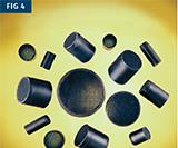
As an alternative to machined vents, sintered metal vent inserts can have thousands of holes for venting.
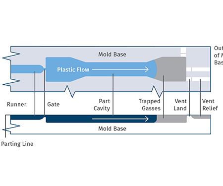
Traditional machined vent design. The key is to allow air and volatiles to escape fast enough to prevent burning (“dieseling”) the plastic.


Conventional vent channels ground into land surface around parting line must be too thin to flash.
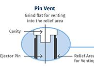
Venting around ejector pins typically involves three flats ground on the pins about 0.001 in. deep and extending down into the relief area.
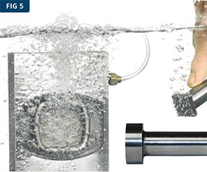
Porcerax II is a proprietary sintered metal with an interconnected network of internal pores, almost like a dense sponge (see microphotograph). It can be machined into “self-venting” pins or core/cavity blocks that allow passage of gases through the apparently solid metal. Hooking up an air line to a block of Porcerax II releases a cloud of bubbles when the block is submerged in water. (Photos: DME and International Mold Steel)


Common part-quality issues such as burns, flash, and warpage cause frequent headaches for molders. Fortunately, careful consideration of one key aspect of mold design—venting—can help eliminate these problems.
Venting is a small part of tool design that has a large effect on part quality, and the number of vents and their locations are therefore critical. But not all plastics designers and processors pay close enough attention to this crucial design aspect.
Inadequate venting traps air, steam from resin, and nonaqueous volatiles (NAVs)—gases from resin and/or additives. These can cause many problems:


• GAS BURNS are black carbon marks caused by the plastic burning (“dieseling”) due to compressed gases. These burns can be more than a surface issue if the mold becomes damaged as the chemical action of the gases etches away the steel underneath.
• PLATEOUT is a film deposit of chemical solids on the cavity. These deposits, most often seen on clear polycarbonate parts, can leave a cloudy mark on the part. Issues with plateout are often seen near the gate due to an initial influx of hot gases.
• FLASH occurs especially when molding thin-wall parts. This common problem is a result of material running out of room in the mold, due to gas that should have been expelled occupying part of the cavity space.
• SHORT SHOTS happen when gas compression in the cavity adds resistance to polymer flow, slowing the cavity fill rate and allowing the melt front to cool before the part is full. When this occurs, viscosity rises and more pressure is required to fill the part.
• OILY BUILDUP, a gummy or sticky substance, can build up near the venting locations and can plug the vent openings. This usually occurs due to overheating.
Aside from location, there is virtually no limitation on venting options. Vents should not be placed where part function, cosmetics, or flash may be a problem. Beyond that, however, venting should be used as much as possible to avoid the aforementioned part quality issues. How you do it is the only open question. This article will look at two common venting options—using traditional machined vents and venting through porous materials—to help you decide which is right for your application.
TRADITIONAL MACHINES VENTS
One of the most common ways of adding venting is by manually machining it into the mold (Figs. 1-3). A parting-line vent is the most common type of machined vent. In this setup, the best location for a vent is opposite the gate, where the part gets filled last.
Another machined venting option involves grinding a small vent channel around the parting line, yet this method will only work with a limited number of resins and the channel must be thin enough not to flash. Still another area for traditional machined vents is around and down along ejector pins, which vent through the mold flats to the outside of the mold.
Traditional machined venting has certain limitations. Ejector pins and ground vents are in fixed positions and can’t be moved if the venting proves to be insufficient. The size and locations of machined vents are sometimes the result of trial and error, which can add time and cost to your process. Machined venting can close off if not properly maintained. And finally, the complexities of machining vents in some locations—such as at the runner, at deep ribs, in corners, in thick fill areas, and at weld locations—present additional challenges.
VENTING THROUGH POROUS MATERIALS
As an alternative to machining, mold components such as vent plugs can be produced from sintered metals (Fig. 4). The conventional approach is to compact and sinter metal powder around an array of copper wires. After sintering, the wires are pulled out, leaving tiny tubular “pores” straight through the sintered plugs. Sintered vents can be up to 0.59-in. diam. and have anywhere from 70 to 10,000 holes for venting. The venting area can be made larger than with machined vents. Sintered vents also minimize flow and knit lines while reducing clamping pressure and cycle time by reducing backpressure.
Perhaps one of the biggest benefits of sintered vents is that they’re easy to remove from the mold for cleaning. When the vents get clogged, they can be cleaned mechanically or chemically by baking at low temperatures, using ultrasonic cleaning, or MEK (methyl ethyl ketone) solvent (also called butanone). Remember to dry out the solvent afterwards. And keep in mind that after repeated cleanings, the pores may start to clog—time to replace the plugs.
Another advantage of sintered vents is that they can be used with slides and lifters. However, their performance will vary with resin grade and viscosity, and they cannot be ground or milled, or the vent pores will become clogged.
Certain materials are considered “friendly” to sintered vents:
• ABS
• Acrylic
• Biodegradable polymers
• Flexible PVC
• Nylon 6, 66, etc.
• Polyethylene
• Polypropylene
• Polystyrene
• PPO Alloy
On the other hand, sticky materials such as liquid polyurethanes should not be used. Rubber, LSR, rigid PVC, polycarbonate, and talc-filled resins can also be problematic with sintered vents.
Another porous venting option is a proprietary sintered metal called Porcerax II (supplied by Sintokogio Ltd. of Japan and International Mold Steel, Florence, Ky. DME supplies pins, blocks, and inserts of this material.). Its internal structure after sintering contains a network of pores or air spaces, almost like a dense sponge. Porcerax II is heat treated to 30-40 HRC with porosity of around 20-30% by volume. The interconnected pores have an average diameter of 7 or 20 microns.
Because the material is composed of 25% air by volume, it vents gas without the need for fabricated holes, or even a separate venting component such as a plug. Entire core pins or core/cavity blocks made of Porcerax II appear to be solid but allow passage of gasses through the mass of metal (Fig. 5). As a result, “self-venting” core pins and inserts of Porcerax II help reduce mold size, cost, and complexity.
Porcerax II provides a location-specific method of venting gas in a targeted area, where one-fourth of the surface area becomes a vent. The larger the surface area of the Porcerax II insert, the greater the venting capacity. The grade with 20-micron pores offers about 25% greater venting capacity than an equal surface area with 7-micron pores.
This method of venting delivers numerous benefits, including reduced injection pressure, as well as substantially reducing scrap and reject rates. Utilizing Porcerax II for core pins and plugs also enhances part production similarly to using sintered vents by preventing burning and shrinkage, preventing flow and knit lines, reducing cycle time, eliminating short shots, enhancing part appearance, reducing gloss, and aiding in part ejection.
What’s more, Porcerax II can be machined by conventional methods. EDM, texturing, or stoning are effective ways to open the pores after machining. Rigid PVC, phenolics, and natural rubber will work with Porcerax II, but only until the corrosive gases clog the pores. Use of rigid PVC, clear polycarbonate, LSR, and foaming urethanes should be avoided with Porcerax II. For low-viscosity or talc-filled resins, it may be necessary to have an automated system to reverse the airflow after each shot.
Keep in mind that the shorter the distance through the Porcerax II to the exhaust line, the better. And water lines should not be run through Porcerax II, since they are difficult to seal and will rust the material.
This type of porous-metal vent material must be cleaned when the tool shop has first prepared the insert or cavity, and also after the insert or cavity has been in operation and a thin film of mold release, resin residue, shop oil, or other contaminant has partially or totally blocked the airflow.
SEVEN RULES OF EFFECTIVE VENTING
To conclude, traditional machined vents, sintered vents, and porous pins and plugs all have their place, depending on the part, flow path, and plastic material. The right approach will vary depending on your material and your process, so collaboration among material supplier, moldmaker, part designer, and molder to determine proper venting is essential.
Here are seven general guidelines to keep in mind regardless of the type of venting option you’re using:
1. Provide as many pathways as possible with sufficient area to allow trapped air and gases to escape from the mold quickly and cleanly.
2. The pathways should lead from the edge of the cavity directly to the outside of the mold.
3. Vents must be deep enough to let out air and gases, but not deep enough to let out plastic.
4. Vents should be regularly inspected and cleaned to prevent buildup.
5. Pay attention to excessive clamp pressures that can close vents.
6. Don’t forget to vent the runner, sprue, and cold-slug wells. This will help the plastic to inject quickly at lower pressures, reduce backpressure, improve flow rate, reduce part stress, and shorten cycle times.
7. Review inserts, slides, and cores for venting, too.


Related Content

Tunnel Gates for Mold Designers, Part 1
Of all the gate types, tunnel gates are the most misunderstood. Here’s what you need to know to choose the best design for your application.
Read More
A Simpler Way to Calculate Shot Size vs. Barrel Capacity
Let’s take another look at this seemingly dull but oh-so-crucial topic.
Read More
Improve The Cooling Performance Of Your Molds
Need to figure out your mold-cooling energy requirements for the various polymers you run? What about sizing cooling circuits so they provide adequate cooling capacity? Learn the tricks of the trade here.
Read More
The Effects of Temperature
The polymers we work with follow the same principles as the body: the hotter the environment becomes, the less performance we can expect.
Read MoreRead Next

Advanced Recycling: Beyond Pyrolysis
Consumer-product brand owners increasingly see advanced chemical recycling as a necessary complement to mechanical recycling if they are to meet ambitious goals for a circular economy in the next decade. Dozens of technology providers are developing new technologies to overcome the limitations of existing pyrolysis methods and to commercialize various alternative approaches to chemical recycling of plastics.
Read More
How Polymer Melts in Single-Screw Extruders
Understanding how polymer melts in a single-screw extruder could help you optimize your screw design to eliminate defect-causing solid polymer fragments.
Read More
Processor Turns to AI to Help Keep Machines Humming
At captive processor McConkey, a new generation of artificial intelligence models, highlighted by ChatGPT, is helping it wade through the shortage of skilled labor and keep its production lines churning out good parts.
Read More