Coping with Weak Weld Lines
Injection Molding Know How
Weld lines cause significant reject rates and are a common problem that all molders face.
.jpg;width=70;height=70;mode=crop;format=webp)
Weld lines are where two flow fronts come together. They cause significant reject rates and are a common problem that all molders face. Minimizing or solving them involves all five of what we commonly call the “Key Components of a Successful Plastic Application.”


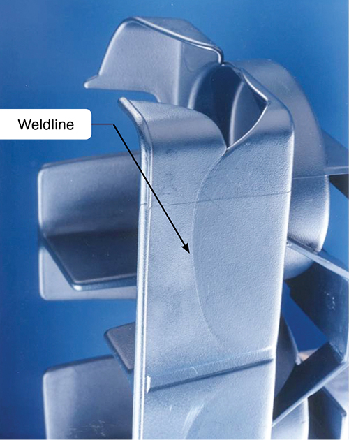
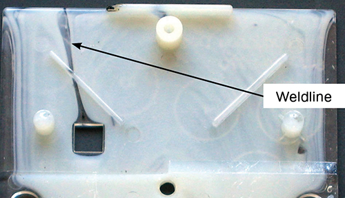
Weld lines are where two flow fronts come together. Often the result is a “witness” line, also referred to as a flow line, knit line, meld line, etc. Weld lines cause significant reject rates and are a common problem that all molders face. Weld lines significantly weaken the structural integrity of a molded part and have resulted in liability issues. Part cosmetics are also usually compromised; weld lines can look like a fine scratch, a gloss differential, blush, haze, or discoloration steak.
The reasons weld lines are weak has nothing to do with the temperature of the flow fronts bumping into one another. The flow fronts do not have an opportunity to cool; plastic flows like lava—it rolls out, exposing fresh hot melt. So the hottest material is constantly being exposed as the flow front progresses. (It is this phenomenon that allows in-mold labeling.) The main reason for weld-line weakness is a lack of polymer chain entanglement across the junction of the two flow fronts. A major contributing factor is air entrapped at this junction; the flow-fronts do not actually meet due to gas trapped between the fronts. Sophisticated microscopic analysis has shown air entrapment even in “good” parts.


Weld lines are one of the most difficult defects to eliminate. Their cause, strength, and appearance are influenced by each of the five “Key Components of a Successful Plastic Application.” These components are:
•Part design,
•Tool design and construction,
•Material selection and handling,
•Processing,
•Testing.
Since minimizing or solving weld-line issues deals with all five, let us address each individually and learn its role in the root causes.
PART DESIGN
To minimize effects of weld lines, the designer must consider part performance and filling or flow pattern of the plastic as it enters and flows through the mold, as well as tooling issues. Plastic part design is a challenge to marry the product performance and marketing demands with manufacturability. For example, large parts often need multiple gates, and multiple gates create weld lines and possibly a cosmetic blemish. And we often design plastics parts with features to aid in assembly, so parts have projections off the nominal wall, like bosses and ribs, as well as holes or depressions.
Projections, depressions, and changes in nominal wall thickness create flow interruptions, which also lead to weld lines. All of these conditions must be considered with respect to the flow pattern upon filling the cavity. The flow pattern plus performance requirements are further complicated by mold manufacturing restrictions. (When you are designing the part you are also designing the mold!) Tough decisions and hard compromises have to made at this stage if the part is to perform as expected.
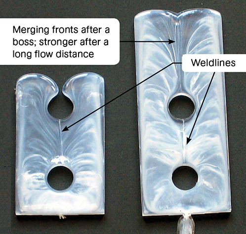
With so much to consider, where does one start? First, minimize flow interruptions and place them such that the flow fronts are allowed to meet and flow some distance after the interruption. Ribs should be oriented in the direction of flow for ease of filling and venting. Those are easy design criteria to state, but they often require difficult compromises between the customer, designer, and moldmaker. Communication between these functions is critical but often nonexistent.
TOOL DESIGN & CONSTRUCTION
As stated, tool design must be considered concurrent with part design. A large part may have multiple gates, resulting in weld lines. If the cosmetics and performance are critical, the weld lines can be eliminated by employing a valve-gated hot-runner system with sequential filling. In multi-gate, cold-runner molds, there will be weld lines. The customer, designer, and moldmaker have to work together to ensure the weld lines will be in areas of least stress or cosmetic importance. If that’s not possible, it may be best to use a post-molding operation, like drilling a hole rather than molding it in.
One bright spot is that today’s mold-filling analysis programs do a great job of pointing out where the weld lines will be; there is no longer any reason for surprises in finding a weld line when the tool is trialed. Optimize strength by picking a gate location that allows flow for a long distance after the flow interruption. This allows more of the chains to entangle across the weld line.
Sometimes it is worth the hassle of adding a flow tab to provide a place to allow the flow fronts to “knit” a bit better. This flow tab has to be cut off after molding, which is another operation and expense but does provide a valuable vent for trapped air as the flow fronts meet. All weld lines trap air, and it is a critical tooling issue to properly vent the area near a weld line. This includes venting core pins, blind holes, and ribs. Venting is one tooling issue not to be compromised: If necessary, provide for vacuum venting.
MATERIAL SELECTION & HANDLING
Different resins can have drastically different weld-line strengths. Tensile testing of dual-gated tensile bars can provide information on weld-line strength retention. Some soft-touch materials are shear sensitive and can provide a weld-line appearance even when there is no flow-front interruption; a “weld line” can appear with a change of shear rate.
If so, look for an alternative resin. Weld-line strength for plastics can vary from 20% to nearly 100% of the strength of the plastic itself. Neat polypropylene retains nearly 90% of its strength on a properly designed and molded weld line. But add 30% glass and weld-line strength retention drops to only 34% as high as the compound with no weld line. Glass filler improves strength over the neat resin but reduces weld line strength; it does not improve it.
PROCESSING INFLUENCES
Processing can affect the strength and cosmetics of weld lines, but it cannot eliminate the root causes. Processing variations in temperature and pressure usually can provide only marginal results. The root causes are poor polymer chain entanglement across the weld line and air entrapment. Both of these root causes must be resolved in part design or tooling.
While many processors like to raise melt temperature to improve weld-line strength, the increase of volatiles coming off the polymer often actually decreases weld-line strength.
First, if at all possible, make sure the weld line is formed during the first stage of fill. Creating a strong weld line during pack and hold is often problematic. Along with getting the weld line formed during first-stage fill, it often helps to increase the injection velocity, thus decreasing the fill time and increasing the shear rate. This lowers the viscosity of the polymer during fill, which in turn allows for better chain entanglement and better packing.
Occasionally increasing pack or hold pressure helps. If it is a cosmetic issue, a slower injection velocity may help, but often a higher mold temperature provides better results. Vacuum venting is a rare but a powerful tool that is even more effective and aids in cosmetics and strength. It should be planned for any anticipated weld-line issues with a part or tool.
Related Content

The Strain Rate Effect
The rate of loading for a plastic material is a key component of how we perceive its performance.
Read More
Are Your Sprue or Parts Sticking? Here Are Some Solutions
When a sprue or part sticks, the result of trying to unstick it is often more scratches or undercuts, making the problem worse and the fix more costly. Here’s how to set up a proper procedure for this sticky wicket.
Read More
Why (and What) You Need to Dry
Other than polyolefins, almost every other polymer exhibits some level of polarity and therefore can absorb a certain amount of moisture from the atmosphere. Here’s a look at some of these materials, and what needs to be done to dry them.
Read More
Tunnel Gates for Mold Designers, Part 1
Of all the gate types, tunnel gates are the most misunderstood. Here’s what you need to know to choose the best design for your application.
Read MoreRead Next

People 4.0 – How to Get Buy-In from Your Staff for Industry 4.0 Systems
Implementing a production monitoring system as the foundation of a ‘smart factory’ is about integrating people with new technology as much as it is about integrating machines and computers. Here are tips from a company that has gone through the process.
Read More
Understanding Melting in Single-Screw Extruders
You can better visualize the melting process by “flipping” the observation point so that the barrel appears to be turning clockwise around a stationary screw.
Read More
How Polymer Melts in Single-Screw Extruders
Understanding how polymer melts in a single-screw extruder could help you optimize your screw design to eliminate defect-causing solid polymer fragments.
Read More