INJECTION MOLDING: Gate-Seal Testing Done Right
Follow these 16 steps to perform the experiment and learn what is best for your part and process.
.jpg;width=70;height=70;mode=crop;format=webp)


With Scientific Molding, two stages are used to form the part: First stage is for getting most of the plastic into the part, normally 90% to 99.9% full by volume. Second stage packs the part to mimic the steel cavity texture and shape. Optimizing the second stage—also referred to as pack and hold—involves moving relatively little plastic into the cavity, but it’s critically important for surface finish, cosmetics, and part dimensions.
Optimizing second stage requires data to establish four process parameters:


1. How should you switch over from first
to second stage (covered in a previous column—Oct. ’14).
2. Should the part be run with the gate sealed (frozen) or unsealed?
3. How much hold time is need?
4. How much pressure is required to pack the cavity properly?
Since I’ve already discussed switchover, let’s focus on the second parameter: gate sealed (frozen) or unsealed (unfrozen). Most of us were taught to always run with the gate sealed so as not to let any plastic backflow out of the gate. Gate seal does provide an easier process to run, but do not make this decision based on what you like, but on what is best for the part. Part performance requirements overrule.
Maybe you can tell which way to go by looking at the part, gate, or runner—but I can’t. It’s a complicated question and I gave up guessing years ago. The area around the gate often has drastically different physical and chemical properties, due to being highly stressed. It should not see high loads, flexing, or impact. It is important that the mold maker understand the function of the part for proper gate location in the mold design.
How do you get the part to tell you what it likes best? The answer is to do the gate-seal experiment and then test parts made with and without gate seal. The data will tell you what is needed and will allow you to make better parts. This will save you time and money by eliminating one variable/factor in your design of experiments (DOE). Heck, it might even prevent a product recall. The whole concept behind Scientific Molding is to find an experiment that tells you what is best for the part and process. The gate-seal test isn’t hard to do, but like many molding issues, you need to sweat the details.
Here is my guideline for the procedure. It may have to be modified to suit your application.
1. Check that timers are functioning correctly and that they span the appropriate time for the part.
2. Make sure you have a cushion and will not bottom the screw
(the check valve should not leak).
3. Make sure that the part is not being filled or packed during screw rotate or plastication if you have to run with a long screw delay before screw rotation.
4. Note overall cycle time, average screw rotate or recovery time, and total pack and hold (second-stage) time.
5. Find the sum of second-stage time and cooling or mold-closed time. The minimum cooling or mold closed time should be a little longer than the actual screw rotate or recovery time. Example: Existing pack and hold timer(s) at 7 sec. If the cooling timer is set for 20 sec and the screw rotate time is 12 sec, the total for second-stage and cooling is 27 sec. Next, in this example, set the cooling or mold closed timer to 26.8 sec and the second-stage timer 0.2 sec. The minimum cooling time will be 13 sec, as it takes 12 sec to charge the shot, and you do not want cycle time to be dependent on screw recovery.
We’ll show how to get to that minimum cooling time in subsequent steps. Note: Cycle time should not change during this experiment, unless you have a very long gate-seal time—in this case, more than 14 sec.
6. With the second-stage timer at 0.2 sec and the cooling timer at 26.8 sec, get the process on cycle. Cycle time should be constant. Note that the sum of the cure timer and pack and hold timer(s) will always equal 27 sec (in this example).
7. Did the cycle time change from the normal cycle time after your adjustments? If so, redo the steps above. Cycle time should not change during the experiment, except for the one or two shots made as you change timer settings.
8. Set up pack/hold pressure to a nominal value by starting low and raising hold pressure until the part “looks” acceptable. Most likely this is not the pressure that will be used to make production parts; it is only for this experiment. Do not use any bogus rules like, “Hold or second-stage pressure should be 50% of fill pressure.”
9. Once the machine is at steady-state, take two sample shots. Cut the runner off if it has a cold runner and label both runner and part with the hold time. If it must be clipped off, do it identically for all samples. For multi-cavity tools, it is your choice to sample cavities individually—which I recommend if you suspect different cavity temperatures or different gate sizes—or all cavities together. I tend to sample all cavities together unless there are reasons to suspect a problem.
10. Remove 1-2 sec from the cooling timer and add the same 1-2 sec to the second-stage timer. The time intervals you use should be appropriate for the part. Again take two samples and write the new second-stage time on each set of parts and runner (if any).
11. Repeat step 10 until the part weight does not increase (for cold runners) or increases only slightly (for hot runners). Cycle time should be unchanged throughout the study. However if you still do not have gate seal—that is, the part(s) stopped increasing in weight—continue to add hold time, extending the cycle slightly.
12. Verify the mold is not being packed out during screw recovery from backpressure (called intrusion). Weigh parts with and without screw recovery at the shortest pack and hold time. In our example, this would be 0.2 sec.
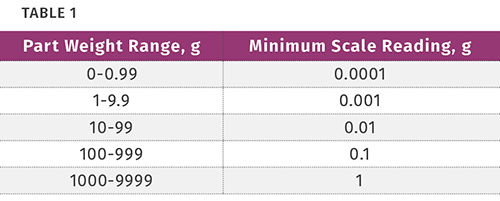
13. Weigh the parts and runners separately, then plot part weight vs. pack and hold (second-stage) time. Make sure you use an appropriate scale. For example:
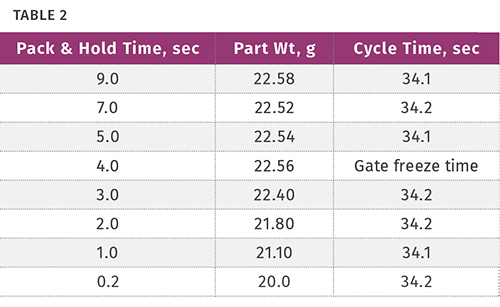
14. Find the second-stage time at which the parts stop gaining weight or start to get lighter. Variation in the last digit of the scale reading is not significant. For example if the part weighs 22.55 g, the part weight must change by 0.1 g to be considered a significant weight change. This time is the gate freeze time. For example:
15. This example shows a gate-freeze time of about 4 sec. This is not where you should set the pack-and-hold or second-stage timer(s). In fact it would be the worst possible choice, as typical temperature and process variations would result in some parts with the gate sealed and some parts with the gate unsealed. It’s critically important to make two sets of parts for testing: One set with gate unfrozen, say at 2 sec of second-stage time and another set made at gate freeze plus 2 sec (in this case, 6 sec).
Thoroughly test both part sets for performance, not size. Set hold time to provide gate freeze or unfreeze, whichever provides the best performance. If you can run with gate freeze, you must be conservative and set second-stage timer(s) to 5 or 6 sec (for this example) to ensure the gate is frozen with normal process-temperature variances.
Remember some parts will run best without gate freeze. If you run with gate unfrozen, the process must run at a consistent cycle time; manual cycles are unacceptable.
16. Now plot the weight of the runner vs. hold time to make sure the runner is not freezing before the gate does. If the runner freezes before the gate, you may not be able to pack out the part properly.
Caution: If different melt or mold temperatures, gate sizes, backpressure, screw speeds, and significantly higher hold pressure or cycle times are implemented, a new gate-seal study must be done. Also, make sure you always have a cushion. With long hold times, the screw can move forward if the check valve leaks.
Bottom line, let the part decide what is best, get data, and study it. There is too much at stake to go with opinions or rules based on myth.
ABOUT THE AUTHOR: JOHN BOZZELLI
John Bozzelli is the founder of Injection Molding Solutions (Scientific Molding) in Midland, Mich., a provider of training and consulting services to injection molders, including LIMS, and other specialties. E-mail john@scientificmolding.com or visit scientificmolding.com.
Related Content

Improve Quality & Productivity With Advanced Screw Design
Most molders are still running with screw designs that haven’t changed much in 30 years. But they don’t need to.
Read More
Are Your Sprue or Parts Sticking? Here Are Some Solutions
When a sprue or part sticks, the result of trying to unstick it is often more scratches or undercuts, making the problem worse and the fix more costly. Here’s how to set up a proper procedure for this sticky wicket.
Read More
How to Set Barrel Zone Temps in Injection Molding
Start by picking a target melt temperature, and double-check data sheets for the resin supplier’s recommendations. Now for the rest...
Read MoreRead Next

Processor Turns to AI to Help Keep Machines Humming
At captive processor McConkey, a new generation of artificial intelligence models, highlighted by ChatGPT, is helping it wade through the shortage of skilled labor and keep its production lines churning out good parts.
Read More
People 4.0 – How to Get Buy-In from Your Staff for Industry 4.0 Systems
Implementing a production monitoring system as the foundation of a ‘smart factory’ is about integrating people with new technology as much as it is about integrating machines and computers. Here are tips from a company that has gone through the process.
Read More
Lead the Conversation, Change the Conversation
Coverage of single-use plastics can be both misleading and demoralizing. Here are 10 tips for changing the perception of the plastics industry at your company and in your community.
Read More