TOOLING: Ejectors: Watch That ‘Unsupported Length’
It may be an unfamiliar term, but it’s the key to preventing ejector-pin deflection and breakage
For years, tool building standards have allowed for insufficient ejector-pin bearing surface, which contributes to tool failures by increasing the unsupported length of the componen
Designing molds to use minimal ejector stroke and relief (providing more bearing surface) will give you a more robust mold and fewer tool failures from ejection on the unsupported length. Using more ejector stroke than needed also just wastes cycle time and increases friction on your components.

To keep ejectors’ unsupported length to a minimum, you can use extensions with small pins or sleeves to reduce deflection and tool failures.
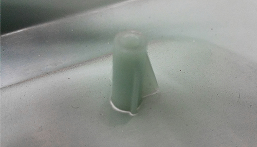
Ejector pin deflection can cause pin read-through, such as the white stress marks around the boss in this photo, showing where the sleeve deflected when trying to eject the boss


Recently I was talking to a tool maker who manages tool repairs in the manufacturing environment. This is a whole different ballgame from working in the tool shop where the pressure of line shutdowns is not always felt. Three of the issues we discussed fall under the topic I will be discussing here, unsupported length of mold components. One issue was a seized ejector pin that crashed with a suicide condition; the others were a broken lifter and a broken 3/32-in. ejector pin. The focus in this article will be on the “Unsupported Length” of ejection. This concern is also relevant to lifters, which I will follow up on in a later article.
OLD STANDARDS NEED UPDATING


When I entered the moldmaking trade in 1988, it was starting to move into the CAD/CAM era. But I consider myself fortunate to have been involved with the pre-CAD/CAM process, as I can see now that some tooling standards carried on when they should have been updated along with technology. Pre-CAD/CAM, tools were cut from cast models on duplicating machines (aka tracers). The hands-on man-hours were a big part of the process back then, with the buildup work, manually made electrodes, spotting, and polishing.
When I was an apprentice, I spent a good part of my life on the radial drill press. This piece of equipment is not very popular nowadays, but back in the 1980s you couldn’t build a large tool without one. A good part of the buildup work was completed on this piece of equipment. When drilling and reaming ejector-pin holes on the radial drill press, the holes would wander slightly, which required adding relief (increasing the diameter for clearance) so the ejector pins would fit smoothly. At times the ejector-pin holes were gun drilled, but in either case we drilled relief (opened up the holes approximately 1/32-in. in diameter) to where there was only 1 to 1.5 in. of bearing surface.
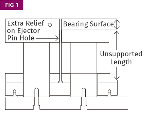
I never questioned this standard use of minimal bearing surface back then because it was needed to get the components to function. But this standard for ejector-pin bearing surface is a contributor to tool failures by increasing the unsupported length of the component. Let me briefly explain “unsupported length,” since many of you readers probably have not heard this term in relation to mold design. I refer to the portion of the component that has no support. The only area of support that resists deflection is where there is bearing surface (Fig. 1).
Please keep an open mind in this discussion. Too many people have been programmed with moldmaking standards that have not evolved with the technology. I was trained myself to accept that you need only 1 to 1.5 in. of bearing surface on an ejector pin. In smaller molds, I have seen as little as 0.5 to 0.75 in. of bearing surface. I never questioned this when I was working in the tool-shop environment, It made sense based on technology in use when I started in the trade. More relief and less bearing surface allowed the components to function freely.
Some of you are no doubt wondering what does this have to do with tool failures. We were all taught that too much bearing surface causes tool failures. I really started digging into this issue when I moved from the tool shop and into the molding environment while still managing mold repairs and preventive maintenance. Whenever an ejector pin galled or broke, I wanted to understand why for future prevention. Based on my experience in building molds, my focus was on the fit of the pin, a straight hole, and alignment with the C bore in the ejector plate and the mold.
Two areas that seemed to cause 80% of the issues were ejector pins that had small diameters or were in the runner with bosses or cold-slug wells. In the case of thin ejector pins, I could understand logically why they might break, but I found the tool design in most cases was a contributor to the small pins breaking.
The runner pin failures took a little bit more effort to figure out, but the root cause is the same—pin deflection. It requires a tremendous amount of force to push out the bosses that have seen thousands of psi of plastic pressure packed against the sidewalls. I have seen a couple of cases where the plastic pressure alone broke the ejector pin during the injection process. The plastic pressure against the pin forced it to deflect and break.
I could give numerous examples of these failures from managing thousands of repairs a year. On larger tools (for a 650-ton press) we had the sprue-puller pin (cold-slug well) that galled and bound up three times, and on each occasion we upsized the pin and reamed the hole. Fit, function, and alignment were not part of the issue. It finally dawned on me that pin deflection was the root cause. So I made the call to eliminate the relief and have 100% bearing surface on the back of the mold, reducing the amount of unsupported pin length. Since that change to address pin deflection, the runner pin on that tool has been a non-issue.
FOCUS ON UNSUPPORTED LENGTH
This is when I really started to look into the “unsupported length” of ejector pins, with my focus on making a robust tool. You really need to understand the amount of force your component may see from the plastic or ejecting the plastic detail. If you have an ejector pin with 4 in. of unsupported length and reduce that to 2 in., the strength of that component more than quadruples. I bring this up because many assume it just doubles.
There are really two things that contribute to unsupported length: too much relief (not enough bearing surface) or more ejector stroke than is needed. The latter has been overlooked in a lot of cases—we just add forward stops to reduce the stroke, right? By adding forward stops, and not reducing the height of the rails to reduce the stroke, you are increasing the unsupported length.
With the same length-to-diameter ratio a 1/32-in. pin is just as strong as a 1-in. diam. pin. But keeping that ratio in mind means that your stroke and unsupported length on the 1/32-in. pin should be drastically less than for the 1-in. pin. If you can design your mold with this in mind, using minimal ejector stroke and relief (providing more bearing surface) will give you a more robust mold and fewer tool failures from ejection on the unsupported length. Using more ejector stroke than needed also just wastes cycle time and increases friction on your components.
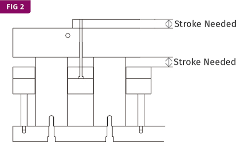
So when designing a tool, if you focus on the stroke needed to eject the part from the mold and use this as your goal for unsupported length of ejection, your deflection issues will be at the minimum (Fig. 2). There are exceptions to all rules, but if possible size the ejector stroke as the distance between the ejector plates and the back of the core half. If stack height is a concern, there are things you can do to increase the stack height without increasing the ejector stroke. I would never consider the distance too small if it meets the stroke required to eject the part. I am not suggesting to keep ejector stroke to its minimum in all cases, but if there is any concern with small-diameter pins or the force needed to eject a part detail, following this rule can make the tool significantly more robust.
For example, if I had a part with 1/32-in. diam. ejector pins and I only needed ½ in. of ejector stroke, that is the distance I would use in the mold design. If I made it any greater I would be asking for problems with pin deflection and tool failure. And remember, less stroke means less friction and less movement, which is time, and time is money.
With ejector pins smaller than 0.125-in. diam., use step pins with the longest shoulder possible. I had a tool that had repeated breakage of 0.062-in. diam. pins. They were step pins using 4-in. shoulders, the longest standard shoulder you could order. So in this case we had custom ejector pins made with 6-in. shoulders to reduce pin deflection and thereby eliminated the pin breakage. (Anytime you use custom components, you should always order extra stock for insurance, since lead times can take up to two weeks.) You can also use extensions (Fig. 3) for small pins or sleeves to reduce deflection and tool failures.
When reducing unsupported length, other details can become more critical and should not be overlooked. Your standard ejector-pin counter-bore in the ejector plate is designed with clearance around the diameter of the head and diameter of the pin so it can float. This is critical to help protect the pin from any minute misalignment or thermal-expansion variances between the mold and ejector plates. Ejector plates will not expand at the same rate as cavity blocks, which can cause interference and binding issues. In some cases, especially on larger tools, you should treat the clearances similarly on guided ejector bushings.
One other issue that pin deflection can cause is pin read-through. This is very tough to diagnose, and I would say this is not a common issue, but many do not even consider this as a possibility. I have also seen stress marks on long ejector-sleeve bosses where the sleeve deflects when trying to eject the boss (Fig. 4). Focusing on reducing unsupported length up front in the design can assist with these issues.
Related Content

Tunnel Gates for Mold Designers, Part 1
Of all the gate types, tunnel gates are the most misunderstood. Here’s what you need to know to choose the best design for your application.
Read More
Where and How to Vent Injection Molds: Part 3
Questioning several “rules of thumb” about venting injection molds.
Read More
How to Start a Hot-Runner Mold That Has No Tip Insulators
Here's a method to assist with efficient dark-to-light color changes on hot-runner systems that are hot-tipped.
Read More
Back to Basics on Mold Venting (Part 2: Shape, Dimensions, Details)
Here’s how to get the most out of your stationary mold vents.
Read MoreRead Next

Processor Turns to AI to Help Keep Machines Humming
At captive processor McConkey, a new generation of artificial intelligence models, highlighted by ChatGPT, is helping it wade through the shortage of skilled labor and keep its production lines churning out good parts.
Read More
People 4.0 – How to Get Buy-In from Your Staff for Industry 4.0 Systems
Implementing a production monitoring system as the foundation of a ‘smart factory’ is about integrating people with new technology as much as it is about integrating machines and computers. Here are tips from a company that has gone through the process.
Read More