
TOOLING: Having Trouble with Lifters?
Lifters can cause tool maintenance, repair, and processing issues if not designed properly. Here we begin a series on how to avoid all this.
Critical elements of tool design with lifters are the lifter angle, travel, and supported/unsupported length.
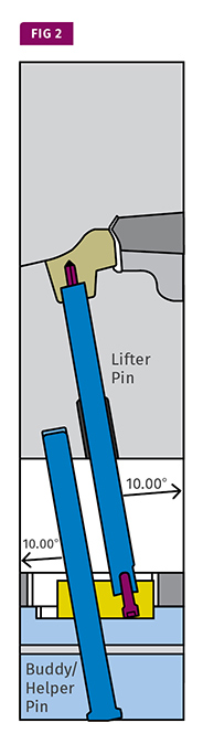
A “buddy” or “helper” pin can help prevent deflection of lifters set at steep angles, minimizing wear and chances of failure.


Lifters are critical components that impact tool maintenance, repair, and injection molding. There is a lot to discuss about lifters: design considerations, materials used, wear surfaces; buddy/helper pins, deflection, shape (round vs. square), part-sticking issues, fitting/spotting, and timing/preload. In this column I will discuss the lifter, why it is used, angles/travel, and some design considerations in relation to the angle/travel.
I manage thousands of preventive-maintenance activities and repairs a year. These involve a wide variety of mold designs from all over the world, running various materials. In the process I have acquired a lot of knowledge with respect to tool designs and how they can impact the manufacturing environment with failures and processing issues. I use the term “red flags and sirens” when I want to label something as a concern. And if there is one component that jumps out more than others with respect to tool maintenance and repairs, it’s the lifter.


When it comes to tool design, most people on the tool-maintenance side prefer slides, if possible. But in cases where lifters are used, slides are usually not an option. I mention this because there have been cases where slides could have been used instead of lifters in a few situations I have encountered.
A lifter is a component that travels with the ejection stroke and moves on an angle to slide/pull cavity steel away from undercuts or details not in die draw where slides or other mechanics are not an option. There are other names for this component, as well as design variations. The design, angle, and materials used for lifters can have a big impact on tool performance over years of operation. I have had many tools run flawlessly with zero lifter issues over millions of cycles. But with other tools I have had nightmares caused by lifters. So the lifter stands out as one component in a mold design that needs a little extra attention.
Some of you may be thinking you have no issues with lifters, but my guess is you are running parts with “lessons learned,” using low-draft lifters with shallow undercuts. In my arena, I am involved with numerous styles of parts and plastic materials across many industries, so we run into some challenging issues with lifters.
LIFTER ANGLE & TRAVEL
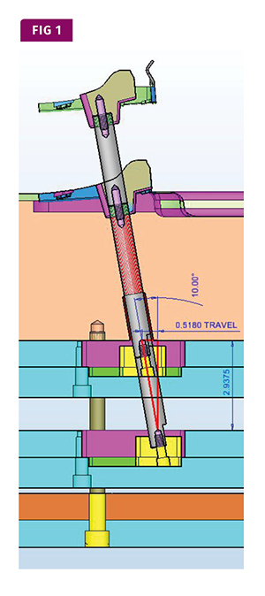
It’s fairly simple math to figure out the angle at which the lifter must move. All you need to know is the depth of the undercut on the part and the ejector stroke being used (or available) with the tool or machine. If, for example, your detail or undercut is 0.5 in. deep, your lifter would need to travel this amount plus clearance so the part will remove freely from the mold without hangups. The amount of clearance needed varies on the size of the part, plastic being used, and shrinkage.
I have seen situations where the clearance was indeed part of the design, but because of part shrinkage the lifters were still engaged, making part-removal very difficult. For example, if you had a PP part 20 in. long, you could have part shrinkage of up to 0.4 in. I stress this because it is sometimes overlooked.
In the example above of the 0.5-in. undercut, if we are going to design a 0.1-in. clearance, our lifter travel would need to be 0.6 in. Let’s also assume we have 4 in. of ejector stroke. I use trigonometry when calculating this, but there is a less complex method: 1 degree will travel approximately 0.017 in. over 1 in. So over 4 in., 1° will travel 0.068 in. We need 0.625 in. over 4 in., so just multiply 0.068 by any number to figure out the angle for our lifter. In this case, we would put the lifter at 9° (9 x 0.068 = 0.612 in. travel).
Now that we understand how angles are determined for lifters, let’s discuss how these angles can impact maintenance. From a mechanical viewpoint, the greater the angle, the more concern about mechanical forces contributing to wear and failures. The unsupported length is just as much a concern as the angle. You could have a steep-angled lifter more robust than a shallow-angle lifter with too much unsupported length. This comes down to the unsupported length/diameter ratio along with the angle of the lifter.
For lifters on steeper angles, you can add a “buddy” or “helper” guide pin to the lifter slide to prevent deflection and keep the slide traveling in the proper position (see Fig. 2). These helper pins are a great option and drastically reduce lifter failures and wear on the rod or shank. I typically would start with at least a 10° angle when considering using a helper pin. But remember that a low-angle lifter with excessive unsupported length could have deflection issues.
In one case, we were having problems with flash under the lifter and with the lifter standing above the cavity surface. This lifter had a 0.5-in.-diam. rod at 3° but had excessive unsupported length. The lifter slide in the ejector plates would not make it all the way home, as the lifter rod was not robust enough and deflected because of the excessive unsupported length. When this happened, the lifter head would not seat all the way and would stand above the cavity surface, causing flash underneath.
There is really no concrete standard to determine when to use helper pins. I use 10° as a reference point, but some lifters with angles under 10° may need them also. And some lifters with angles greater than 10° may not need them.
During tool design, when you determine the lifter angle based on stroke, you need to make sure the unsupported length does not exceed the travel. I have seen many cases where the back plate or mold base is cleared by the lifter rod/shank and the bearing surface is only on the cavity. You should always have a bushing or guide blocks on the back plate or mold base to give the lifter as much support as possible. Lifters can also deflect as a result of cavity pressure, causing read-through on the part. In cases where there is no shutoff shelf on the lifter, cavity pressure can push it below the cavity surface.
Next month, I will get into more specifics on lifters in wear surfaces, materials used, fitting, timing, and more.


Related Content

Optimizing Pack & Hold Times for Hot-Runner & Valve-Gated Molds
Using scientific procedures will help you put an end to all that time-consuming trial and error. Part 1 of 2.
Read More
Back to Basics on Mold Venting (Part 2: Shape, Dimensions, Details)
Here’s how to get the most out of your stationary mold vents.
Read More
Tunnel Gates for Mold Designers, Part 1
Of all the gate types, tunnel gates are the most misunderstood. Here’s what you need to know to choose the best design for your application.
Read More
How to Optimize Pack & Hold Times for Hot-Runner & Valve-Gated Molds
Applying a scientific method to what is typically a trial-and-error process. Part 2 of 2.
Read MoreRead Next

People 4.0 – How to Get Buy-In from Your Staff for Industry 4.0 Systems
Implementing a production monitoring system as the foundation of a ‘smart factory’ is about integrating people with new technology as much as it is about integrating machines and computers. Here are tips from a company that has gone through the process.
Read More
Troubleshooting Screw and Barrel Wear in Extrusion
Extruder screws and barrels will wear over time. If you are seeing a reduction in specific rate and higher discharge temperatures, wear is the likely culprit.
Read More
Understanding Melting in Single-Screw Extruders
You can better visualize the melting process by “flipping” the observation point so that the barrel appears to be turning clockwise around a stationary screw.
Read More