
The Impact of Hydraulics on Tool Design, Practical Uses -- Part 2 of 2
Here are more tips on using hydraulically actuated devices on your tools.


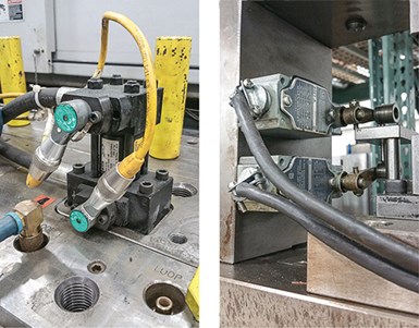
There are typically two styles of switches used with hydraulics for set and pull position: mechanical (left) and proximity. Proximity switches are used because they are compact and part of the cylinder.
Last month’s column concluded with my recommendation that you ensure your hydraulic cylinder is rated for the hydraulic psi being used. In cases where this cannot be done—for example having a cylinder rated for 1500 psi and using 2000 hydraulics psi—you can add an inline pressure-limiting valve on the mold to protect the cylinder from failure. For example, with some hydraulic valve gates, the cylinders are not rated for high pressures. In situations where the cylinder may be rated for the pressure, but that amount of pressure is not needed, you can add this valve to protect your moving component.
One other note to consider from last month’s column concerns bore size: If you are using a double-ended rod, you’ll need to subtract its diameter from the bore size because it reduces the surface area on the set/forward position.


There are also cases also where a self-locking cylinder can be used if you do not have the real estate for the bore size needed to counteract the cavity pressure. This type of cylinder has a mechanical lock-on set that engages the hydraulic piston in place to prevent blowback. I have many tools with these cylinders and have found them to be reliable with minimal maintenance if used properly. Just be aware that they have set/pull pressure specs. For the mechanical-lock feature, timing with your component in the set position is a critical, but very simple, process when installing on the mold.
If you use a T-slot coupler, you can create extra travel in the machined slot and add a spring to hold it in the back position.
Hydraulics are also used instead of knockout bars for ejection in some cases, particularly when the ejection stroke is more than the machine has available. Some molders also use them to reduce setup time with tied-in knockout bars. Others use hydraulics in the reverse-ejection situations, where the ejector plates are on the stationary half of the mold. Reverse ejection is usually deployed because of part criteria; the mold will have a Class A surface and not allow ejector pin marks or direct gating.
There are cases where hydraulics are not needed with reverse ejection, but these require mechanical features via latch locks or other mechanics.
With standard hydraulic ejection on the moving half, I try to stay away from using hydraulic cylinders to stroke the ejector plate. This is purely from a tooling viewpoint; hydraulics can increase maintenance with the extra components, and hydraulic oil is not pleasant to clean up. But there are always exceptions. If hydraulic cylinders are the route you have to take to stroke the ejector plates, use a geared flow-control device. This ensures that the cylinders are getting the same amount of oil and moving at the exact same time to prevent any cocking of the plates.
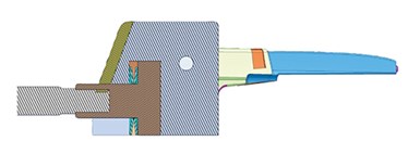
This device can protect critical shutoffs from the set speed/pressures and help protect low-draft shutoffs against the stationary half. The hydraulic cylinder bottoms with the component 0.030-0.060 in. from home position, and the lock angle drives it home on mold close. (Image: Deppe Mold & Tooling, Inc.)
When using hydraulics for core pulls that have shutoffs on the cavity, the shutoff should not be the positive stop that takes all the impact of the hydraulic pressure in the set position. It is best to have a step or ledge on your component that bottoms out at the same time as your shutoff to protect it. Also at times these shutoffs need to be vented, and without the added protection you will just coin it shut over time.
Hydraulics are also used with slides that require excessive travel when the standard mechanical horn pin cannot provide the amount of travel needed. In many cases, the slides will have a lock angle with the stationary half, locking it in place against plastic pressure where the hydraulic pressure is not needed to withstand cavity pressure (see last month’s column).
One area of concern with hydraulically driven slides is when there are low-draft shutoffs between the slide and the stationary half. I have seen this many times, and it can contribute to galling on the shutoff, with the slide being locked forward by hydraulic pressure. In these situations, when adequate draft cannot be added, there is a simple device you can use to protect your component on the set position . If you use a T-slot coupler, you can create extra travel in the machined slot and add a spring to hold it in the back position.
I typically set it up so that the component is 0.030 to 0.060 in. from the home position when the cylinder is bottomed out. When the mold closes, the lock angle on the stationary half will push it in the home position while collapsing the spring (shown here). This will protect the shutoffs from galling. I have also used this same device when the component has critical shutoffs of the moving half to protect them with set speeds and pressures.
When using mounting plates to attach the hydraulic cylinders to the mold, make sure the plate and bolts are robust enough to preventing flexing and broken bolts from the stresses.
When hydraulics are used on a tool, there is a good chance that there will be a suicide/crash condition. If this occurs, repairs can be costly. Using multiple core/hydraulic sequences in this situation can be risky. It is important to label them, color code them—or better yet—use different-size fittings for each sequence so they cannot be set up improperly in the press. Also using male and female connections for set and pull can help distinguish them at setup. It is also important to have a core-sequence plaque on the mold to assist with machine setup.
When using mounting plates to attach the hydraulic cylinders to the mold, make sure the plate and bolts are robust enough to preventing flexing and broken bolts from the stresses. I have witnessed many such failures resulting from inadequate mounting-plate thickness and bolt sizes. And whenever the cylinder rod is attached to the component with threads, make sure the hole is tapped perfectly straight or square. You should also consider doweling the plates in position so everything stays on center of the cylinder. Threads can work loose over time, so Loctite or a set screw can be used to reduce that likelihood.
There are typically two styles of switches used with hydraulics for set and pull position: mechanical and proximity. Mechanical switches typically are my first choice, but proximity switches are used in most cases because they are compact and part of the cylinder. These typically read and sense the position of the piston magnetically, either directly on the piston itself with the sensor bolted in a hole in the wall of the cylinder, or through the cylinder wall when made of aluminum or stainless steel.
When using sensors that are bolted in a fixed position, timing of the component for the set-and-pull position is critical so the piston is in a position where the sensors can read it. Sensors that read through the wall of the cylinder can be adjusted to any position, so timing of the component is not as critical. But when using aluminum cylinders, make sure they will be adequate for the cavity pressures and hydraulic pressures. I try to stay away from these in high-temperature or high-pressure situations because they are not as robust.
When using proximity sensors you also need to consider the temperatures they will be seeing. Most will not read properly at over 150 F. And take care with magnetic proximity sensors: We once had metal chips get inside the lines and a tool crashed because it was reading the false position.


Related Content

How to Optimize Pack & Hold Times for Hot-Runner & Valve-Gated Molds
Applying a scientific method to what is typically a trial-and-error process. Part 2 of 2.
Read More
Hot Runners: A View from the Bottom Up
Addressing hot-runner benefits, improvements, and everyday issues from the perspective of decades of experience with probably every brand on the market. Part 1 of 2.
Read More
Where and How to Vent Injection Molds: Part 3
Questioning several “rules of thumb” about venting injection molds.
Read More
Back to Basics on Mold Venting (Part 2: Shape, Dimensions, Details)
Here’s how to get the most out of your stationary mold vents.
Read MoreRead Next

The Impact of Hydraulics on Tool Design -- Part 1 of 2
Get a better understanding of their use, proper sizing, and how the tool design and setup in the machine can impact failures in manufacturing.
Read More
The Impact of Hydraulics on Tool Design -- Part 1 of 2
Get a better understanding of their use, proper sizing, and how the tool design and setup in the machine can impact failures in manufacturing.
Read More
Understanding Melting in Single-Screw Extruders
You can better visualize the melting process by “flipping” the observation point so that the barrel appears to be turning clockwise around a stationary screw.
Read More