Understanding Intensification Ratio
A first step in taking the “art” out of molding.
.jpg;width=70;height=70;mode=crop;format=webp)


The intensification ratio is equal to the ratio of the effective areas of the hydraulic ram to that of the screw check valve. Since those values often are not readily available, the intensification ratio is also equal to the inverse ratio of hydraulic pressure in the cylinder (not pump) to the resulting plastic pressure in the nozzle.
Many believe injection molding is an art. Perhaps there is an element of truth to that, as there are hundreds of variables in the process and few humans that can deal with them all. However, as the term “Scientific Molding” implies, I work to bring science into processing.
An important piece of this science is the intensification ratio of hydraulic machines. What is intensification ratio? It is the ratio of hydraulic ram area to the screw size area. Note: These are areas, not diameters. More on this later; but some history first.
During my early days of processing, I swore certain molds could read the name on the machine, and if they did not like it they just were not going to make acceptable parts. If the mold went into Machine A, I’d have problems. If it went into Machine B, it was a good day. Why? As it turns out, most early machines were made with a 10:1 ratio of hydraulic ram area to screw area (not diameter). So for a while it did not matter if you used hydraulic pressure (a machine variable) or plastic pressure (a plastic variable) when moving a mold from one machine to another.
Why Knowing the Intensification Ratio Is Critical
However, when I started out, it was at a time when some machine manufactures realized it was cheaper to buy stock hydraulic cylinders rather custom building a hydraulic cylinder to match each different screw for a 10:1 ratio. So with the newer machines. the intensification ratio varied with different screw sizes. Once I learned about intensification ratio, I went back to the shop and calculated them for machines A and B. This took some time as it was, and still is decades later, a hassle to find out exact hydraulic ram areas.
Turns out machine A had an intensification ratio of 10:1, and machine B was 14.6:1. The mold needed 23,000 psi (1585 bar) to fill. Machine A had only 20,000 psi (1380 bar)—not enough. Machine B had 29,200 psi (2014 bar)—some to spare.
It was not Murphy’s Law or art that explained my problems with Machine A, it was physics (science). This was my “aha!” moment that highlighted the difference between machine variables and plastic variables: Duplicate plastic variables, not machine variables, to get consistent parts. It was an embarrassing number of years before the “science” of intensification ratio came to light. I only wish someone had clued me in from the beginning.
Working with plastic variables will solve problems and make processing more understandable. Pressure is one the most important variables in molding. Duplicating plastic pressures will make identical parts. Electric machines are no problem, as there is no hydraulic ram pushing the screw. They read plastic pressure directly. Essentially all electrics have an intensification ratio of 1:1.
Hydraulic machines, on the other hand, work with hydraulic power. Molders need to understand that hydraulic power is converted (multiplied or intensified) into plastic pressure (melt pressure in the nozzle). The law of physics involved is F = P × A. That is, force (F) is equal to pressure (P) multiplied by area (A). The large hydraulic ram pushes the screw, and the non-return valve (check valve) acts as a plunger pushing plastic through the nozzle into the mold.
The hydraulic ram has a large surface area; let’s use 150 cm2 as an example. The non-return valve during injection forward acts as a smaller ram; let’s use 15 cm2. This large-to-small ratio of ram areas intensifies or magnifies the hydraulic pressure as it is converted to plastic pressure in the injection nozzle. Here, hydraulic pressure is intensified or multiplied by a factor of 10. This is the machine’s intensification ratio and explains how several hundred psi of hydraulic pressure can provide thousands of psi plastic pressure inside the nozzle. That is, 800 psi (55 bar) psi of hydraulic pressure
provides roughly 8000 psi (551.7 bar) of melt pressure inside the nozzle.
Most machines today are not 10:1 in intensification ratio.
Today you can buy machines with intensification ratios ranging from 6:1 to 43:1. Custom machines can go even higher. Most machines today are not 10:1. It is plastic pressure that pushes plastic into the sprue, runner, gate, and mold cavity, not hydraulic pressure. This plastic pressure must be duplicated as you go from to machine to machine with the same mold. If your plant has different sizes or makes of machines, most likely they have different intensification ratios. That is, 800 psi (55 bar) pack-and-hold pressure on one machine with an intensification of 10:1 develops 8000 psi (551.7 bar) plastic pressure in the nozzle, but on another machine with an intensification ratio of 12.75:1, 800 psi hydraulic pressure develops 10,200-psi (703 bar) plastic packing pressure in the nozzle. You will not make the same part. To make the same part using the same lot or color etc., you must develop the same nozzle pressure of 8000 psi (551.7 bar). That is, use only 627 psi (about 43 bar) hydraulic pack pressure on the second machine.
Calculate Intensification Ratio
Ideally, you should know the screw diameter and the functional hydraulic ram diameter to calculate the ratio of areas. Unfortunately, you will spend hours looking for the hydraulic ram area and in some cases, it cannot be found in the machine manuals. While this is the best way, it is not practical.
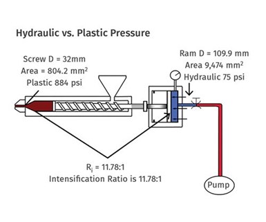
An easier method is to find the machine specifications, identify which diameter screw you have in the machine, and from the machine specifications find the maximum plastic or melt pressure. Machine suppliers have various names for plastic pressure, such as “injection pressure” or “specific pressure.” Then go to the machine and find what maximum hydraulic pressure you are allowed to set for injection or first stage. Do not take it from the machine specifications, as they may list pump pressure, which is different from the pressure in the hydraulic cylinder. Once you have these two numbers you can calculate the machine’s intensification ratio with the following equation (see illustration):
Ri = Maximum injection (plastic) pressure ÷ maximum hydraulic pressure for the injection unit.
From the machine specifications, we find that the maximum injection or plastic pressure possible is (for the sake of example) 26,500 psi. From the machine’s controller we find that the maximum hydraulic pressure we can set for the injection cylinder is 2250 psi. So:
Ri = 26,500 psi/2250 psi = 11.78:1.
To calculate the plastic pressure for backpressure during screw rotation with a machine setting of 75 psi hydraulic, multiply the hydraulic pressure times the intensification ratio. In this case:
Backpressure (plastic) = 75 psi x 11.78 = 884 psi
If you transferred this process to an electric machine, you would have to set 883 psi as the input for backpressure.
Bottom line: For processing plastics, work in plastic pressure using the intensification ratio for hydraulic machines. Hydraulic pressure does not tell you what you need to know. Intensification ratio does and it should even be on your setup sheet. Machine builders need to start putting this critically important number on all their specification sheets. You should not have to waste your time getting the numbers to calculate it.
ABOUT THE AUTHOR: John Bozzelli is the founder of Injection Molding Solutions (Scientific Molding) in Midland, Mich., a provider of training and consulting services to injection molders, including LIMS, and other special- ties. Contact john@scientificmolding.com.
Related Content

Best Methods of Molding Undercuts
Producing plastics parts with undercuts presents distinct challenges for molders.
Read More
What to Do About Weak Weld Lines
Weld or knit lines are perhaps the most common and difficult injection molding defect to eliminate.
Read More
How to Stop Flash
Flashing of a part can occur for several reasons—from variations in the process or material to tooling trouble.
Read More
Understanding the ‘Science’ of Color
And as with all sciences, there are fundamentals that must be considered to do color right. Here’s a helpful start.
Read MoreRead Next

In Search of a Universal Setup Sheet
Duplicating a process from one injection machine to another is frustrating and time-consuming. Develop a mold-specific setup sheet that works in all kinds of presses by differentiating plastic parameters from machine parameters and duplicating those plastic conditions from machine to machine, electric or hydraulic.
Read More
Understanding Melting in Single-Screw Extruders
You can better visualize the melting process by “flipping” the observation point so that the barrel appears to be turning clockwise around a stationary screw.
Read More