Understanding Screw Breakage
Extrusion Know How
You might think you're over-torquing the screw, but more often than not bending is the reason.
Extrusion screws, even those smaller than 2 in. diam., very seldom break. But when they do, what are the causes? Your first guess might be that the screw was compromised due to over-torquing, but in reality bending causes more breakages than over-torquing.
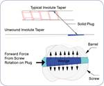
Over-torque failures almost always occur in the feed section, which makes sense because that is screw section most susceptible to torque. Torque failures have characteristics that are easy to identify. They always initiate from the outermost portion of the screw—the flight surface—and crack toward the center. As a result you’ll see radial cracks in the flight surface around the break. Additionally the screw will “wind up” like a spring, and the flight pitch around the break will be permanently reduced (see illustration). As the screw winds up and cracks it also grows in diameter, making it very difficult to remove from the barrel.
There is no exact calculation for screw strength in torsion because of the complex or indeterminate shape of the cross-sectional area. But it can be estimated by assuming that just the root diameter carries the torque load, even though the flight adds to the screw’s torsional strength.
I have found that a safe design can be calculated using simple torque formulas and assuming a maximum allowable shear stress of 50,000 psi. That’s a little over half the yield strength of 4140 heat-treated steel, from which the vast majority of feed screws are made in the U.S.
The formula is: Ss=16T/πD³ where:
T= (hp x 63025)/max screw rpm=in.-lb
D= Diameter of feed-section root=in.
Ss= Shear stress (<50,000)=lb/in.²
This formula applies to a screw without a cooling bore. If a cooling bore is used the following formula works:
Ss=16 TD/π(D4-d4) (d=bore diameter).
The cooling bore has almost no effect on torsional strength because the stress is maximum at the outer surface and zero at the center or neutral axis where the cooling bore is located.
Screw bending or fatigue failures do not typically show radial cracks. These failures generally reveal themselves by a single crack that goes all the way through the screw. In addition, these failures don’t result in the “wind-up” effect or a pitch reduction.
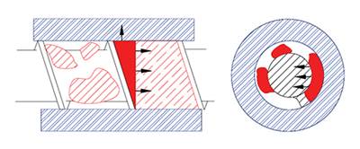
Bending occurs either from the side forces the polymer exerts on the screw during melting, or from misalignment of the barrel. Bending by either mechanism is termed “reversed bending.” Think of the rapid failure caused when you break a wire between your fingers by flexing it back and forth.
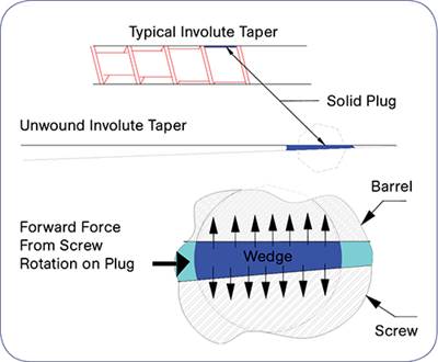
In order for the internal barrel pressures to cause a screw break, the screw/barrel must first be worn enough to provide the clearance necessary for the bending to occur. This may take a long time, but once sufficient clearance is present, breakage quickly follows. I have covered this type of localized wear, called wedging, in previous columns (see links to these articles at the top right-hand side of this page).
The screw is also under torsional load from the drive, adding to the overall stress, since both bending and torsional stresses are at their maximum on the outer surface of the screw. With the combination of the reversible bending stress and torsional stress, failure will occur in very few cycles after the critical stress is reached at the surface. That is typically at about 40% of the normal tensile strength, meaning reversed bending reduces the strength to about half the steel’s specification.
Bending failures due to barrel alignment are similar but can occur sooner because it’s not necessary to wait for the screw and barrel to wear. Interestingly, bending failures usually occur in the strongest sections of the screw, because that’s where it takes the highest force to bend it, with the resulting highest stress at the flight surface. When a screw breaks in one of its thickest or strongest sections, it’s extremely unlikely that it was an over-torque situation alone.
Related Content
Understanding Melting in Single-Screw Extruders
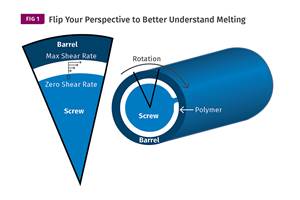
You can better visualize the melting process by “flipping” the observation point so that the barrel appears to be turning clockwise around a stationary screw.
Read MoreUnderstanding the ‘Science’ of Color
And as with all sciences, there are fundamentals that must be considered to do color right. Here’s a helpful start.
Read MoreHow Much L/D Do You Really Need?
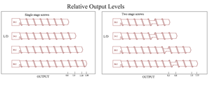
Just like selecting the extruder size and drive combination, the L/D should be carefully evaluated.
Read MoreAvoid Four Common Traps In Granulation
Today, more than ever, granulation is an important step in the total production process. Our expert explains a few of the many common traps to avoid when thinking about granulators
Read MoreRead Next
‘Wedging’ Can Cause Severe Screw Wear
In a column I wrote for the July 2011 issue, I discussed the value of conducting “forensic” examination of worn screws when they are removed for clues to design flaws.
Read MoreDead Screw Talking
There's a lot you can learn by conducting a post-mortum examination of your screw.
Read MoreThe Cause of Catastrophic Screw Wear
Erratic feeding can be the culprit. This is not uncommon when dealing with recycled material.
Read More.jpg;width=70;height=70;mode=crop)
