- Home
- Conveying Equipment News
- System Types
- System Operation
- System Economics
- System Design
- Installation
- Components
- Controls
- FAQ

Troubleshooting an Established System
Click image to enlarge
A well-designed, properly installed, resin conveying system is a real asset and will pay you significant dividends. Following good maintenance practices will maximize performance and up-time. Keep an inventory of the manufacturer's recommended spare parts. On those occasions when something does go wrong, recognizing the source of the problem and following a logical troubleshooting procedure will allow you to take corrective measures promptly and keep your plant running smoothly.
The best way to avoid materials handling problems is to design and install the system properly in the beginning. See System Design.
When a working system develops a problem, it is because something has changed. Typically, one or more stations suddenly are not filling properly. Your first instinct may be to lengthen the load time. That will not solve the problem. Instead ask, 'What has changed?'
Drop in Throughput
Pelletized materials require sufficient air to be transported. Insufficient air will cause the material to surge in the lines, but the surging is offset by the 'lull' in the flow so the overall effect is lower throughput. Try the following:
- Increase air flow
The cure may seem counterintuitive: Gradually increase the air in the lines by adjusting the air mixing valve at the material source, and the throughput will usually increase. - Check for clogged filters
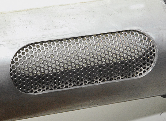
Clogged filters in vacuum receivers, vacuum takeoff boxes, and vacuum pumps are the most frequent cause of reduced throughput. Inspect and clean them on a regular basis. - Empty the catch pans under cyclone filters if you have them. If the pans fill up, dust can be pulled back through the system to clog the filters.
- Check the vacuum in the system
A loss of vacuum will also cause throughput to drop. Verify that the gauge on the vacuum pump is reading between 5 and 9 in. of Hg while the system is running. A lower reading indicates a vacuum leak.
To check vacuum in the system:
- a. Remove the vacuum line from the inlet to the cyclone.
- b. Cap off the cyclone inlet (use duct tape, or cover it with your hand).
- c. Activate the pump using the pump “Start” button. The high vacuum relief should open. (It will sound like a bird chirping). This will let you know the pump is sealed properly. The vacuum gauge should go to 12 in. of Hg (or higher on larger pumps).
- d. If the vacuum relief doesn’t open, there is an air leak at the pump.
- e. Check the seal on the dump can on the cyclone, the filter-housing lid seal at the pump, the vacuum breaker valve (verify it has air at 85 to 100 psi), and all piping connections.
- f. If the relief valve opens, reconnect the vacuum line to the system and do the same check. If the relief valve opens, the system is sealed and all station “T” valves are closed.
- g. If the valve doesn’t open, you have a vacuum leak. Check the system for any open lines, open station valves, or lack of air to the station ‘T’ valves.
- h. Make sure that all vacuum receivers are sealed, all hose and pipe connections are tight, and look for holes in material lines that can be caused by glass-filled materials or conveying velocities being too high. Use stainless or ceramic elbows for abrasive resins.
Plugged material lines
This problem is typically related to a lack of transport air. The surging described above can actually pack material into the lines. With virgin pellets, simply remove the material line from the material source and the plug should break up. If this works, slightly increase the air flow by adjusting the air mixing valve to avoid a repeat of the problem.
Regrind material and even virgin material can pack in the lines hard enough to require manual removal. The plug has to be isolated and each end of the affected pipe or pipes must be opened and the material forced out with a rod. This is a labor-intensive job and it shuts down production so it should be avoided. Remember, sufficient transport air is the best preventative and usually the cure.
NOTE: If the problem persists ' consider replacing your current vacuum pump with an Ultra-High Efficiency Pump.
Starved' vacuum receivers
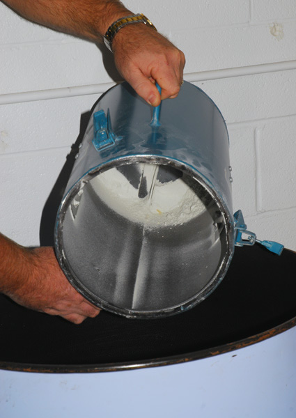
If material is not reaching vacuum receivers beyond a particular station in a common-line system, check for an overfilled vacuum chamber. A reverse-flow check valve is typically located inside the vacuum receiver at the material inlet, and filling the vacuum chamber above this check valve will cause the check valve to be held open when another receiver attempts to load from the shared line. The resulting vacuum loss will prevent material conveyance to all other stations on the shared line. Receivers should be filled to nearly to the level of the check valve but not above it.
Decrease the load time; or, if the amount of material loaded in a single shot needs to be increased. You ca also add a spacer below the check valve or switch to a larger receiver.
NOTE: If the problem persists ' consider replacing your current vacuum pump with an Ultra-High Efficiency Pump.
Four-Way Control Solenoid Failure
One of the most common problems in pneumatic conveying systems is four-way control solenoid failure. This is usually caused by foreign particles originating in the compressed-air lines and usually occurs during installation and start-up. The four-way solenoid valve that is used to control station valves and other similar valves requires clean, dry, oil-free air to operate properly. Installing a compressed-air filter/separator can virtually eliminate such problems with these valves.
Use of JIT Receivers
JIT (Just-in-Time) machine mount receivers work best when used in a dedicated material line system. The potential problem when they are used in common line systems is that some material tends to miss the turn at a lateral (or 'Y') pipe like a driver missing an exit. When the vacuum ceases down this leg, this 'bypass material' will come to a rest just past the 'Y.' This creates a problem for JIT systems because the bypass material can be more than the shot size (often 1 lb. or less), causing the station to repeatedly call for material. A station farther down the line may clear the bypass material, overfilling its small JIT receiver and holding the check valve open. A common line can usually be used with larger machine mount receivers because when enough material misses the turn, the remaining material will be forced to make the turn at the lateral, and when the bypass material does clear, it usually won't overfill a larger receiver.
If the ‘over-filling” condition becomes chronic, the best solution is to install a diverter valve in place of the standard lateral pipe. The diverter is automatically actuated to force material assigned to a particular station to go to that station. You can also use a common line diverter, which is a static parallel “Y” and elbow fitting assembly that prevents excessive manifold plugs from forming. It does this by diverting the main material manifold around each station drop, which creates a small, repeatable and manageable material plug at each station, which is easily cleared when that station fills.
Still, dedicated material lines should be used for JIT applications to pre-empt this problem.