
Hitting the Numbers, Part 2: The Shrinkage Factor
The shrinkage factor is one of the most critical numbers to hit.

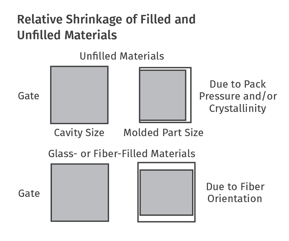
If the material is glass or fiber filled, the anisotropic shrinkage will be less than for unfilled materials, but the difference between the two directions is considerably greater and the directions are reversed—much less shrinkage in the direction of flow and much more perpendicular to the direction of flow.
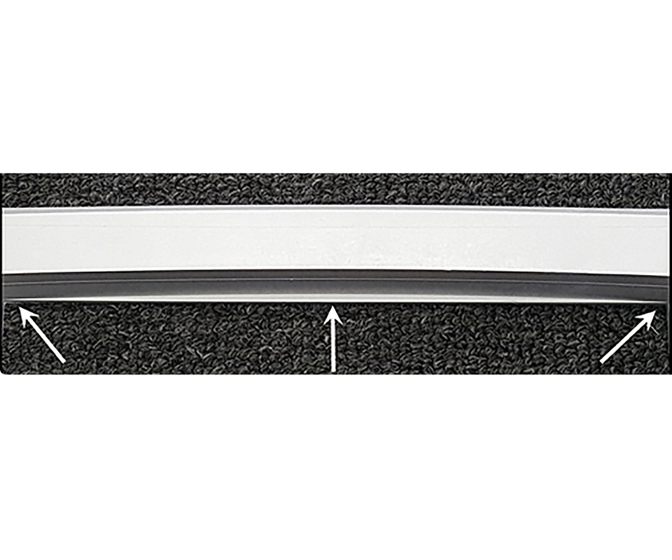
This part bowed outward so much, a convex “windage” rib was machined into the mold by the amount of the bow. The rib straightened out after the part was ejected and cooled.


This is part two of a two-part series discussing the best practices for Hitting Critical Numbers. For part one of this series read this article.
In part one of this series, I focused on critical dimensions, dimensional tolerances, moldability, functionality and material options, all of which can make you miss your numbers. Here, I’ll address the big elephant in the room: Who specifies and is accountable for the shrinkage factor?
The shrinkage factor is one of the most important numbers to hit. It can cause lost profits, high scrap rates and heated discussions between the customer, the toolmaker and the molder. In my 40 years in the injection molding business, I have not experienced one occasion in which the customer has specified the shrinkage factor—unless the customer was also a molder.
Material suppliers can’t be held accountable for specifying the shrinkage factor. There are too many variables over which they have no control. In addition to the part thickness, flow length and gate size, processing parameters such as melt temperature, mold temperature, fill time, hold time, hold pressure, cooling time (actually cooling rate) and backpressure all have an effect on how much a part will shrink. The supplier has technical data sheets, which aren’t all that technical. They typically give a shrinkage range, not a specific value, such as: “Molding Shrinkage: 0.004-to-0.006 in./in. as per ASTM D955.” Those values are based on the shrinkage of a 5" × 1⁄2" × 1⁄8". test bar, edge gated on the end. Unless you’re molding 1⁄8" thick test bars gated on the end, the shrinkage range specified by the material supplier can only be used as a reference.
The toolmaker doesn’t have much control over the molding parameters, either. That’s why most toolmakers ask the molder to specify the shrinkage factor. An experienced molder deals with a lot more molds and materials then a toolmaker does, and will have a better prediction of the results. The molder can also suggest the gate location or the use of multiple gates, particularly if the part is large or made of a glass-filled material.
If the molder has a tool with similar part design, sample it in the material for the new job. It’s a quick and inexpensive way to estimate shrinkage values. Take several measurements in both directions and at various depths. The formulas for determining the shrinkage values are:
Shrinkage Ratio = (Steel Dimension–Part Dimension)/Steel Dimension
Shrinkage Percentage = (Steel Dimension–Part Dimension) × 100/Steel Dimension
The second largest attribute affecting material shrinkage is wall thickness. Ask the material supplier if he has a graph showing wall thickness vs. shrinkage factor. You might get lucky. Many suppliers have graphs showing wall thickness vs. flow length or cycle time, but only a few will have one for shrinkage. Uneven walls have uneven shrinkage, which is one of the primary reasons for sink marks and warpage. Coring out a part to obtain a uniform wall thickness is essential to hitting the numbers and avoiding a host of other problems.
The largest attribute that effects shrinkage is obviously the material itself. Amorphous materials, such as PS, ABS, PC and PVC, shrink a relatively small amount and for the most part, shrink isotropically (uniformly in all directions). If, for example, the specified shrinkage ratio range was 0.004-to-0.006 in./in. and the wall thickness of the part was between 0.060" and 0.120" and uniform, a molder might suggest using 0.004 in./in. for the thinner part, or 0.006 in./in. for the thicker part, and he’s probably going to be pretty accurate. If he’s a little off, it’s probably because he didn’t account for cavity pressure. Parts will shrink less in thin and well-packed areas, such as near the gate. They will shrink more in thicker and under-packed areas, such as at the end of fill.
If the material is semi-crystalline, such as PP, PE, PBT, POM (acetal), or PPS, the shrinkage factor needs serious consideration. Crystalline materials shrink much more than amorphous materials and they shrink anisotropically—more parallel to the direction of flow and less perpendicular to the direction of flow. The shrinkage factor is now shrinkage factors. Using the average of the two values will probably make the part out of spec in both directions.
Understanding the characteristics of the molding material is paramount to hitting the numbers. For example, if the material is PEEK or PPS, depending on the wall thickness, mold temperature, and cooling rate, these materials can be either amorphous or semi-crystalline, which will affect the mechanical properties, chemical resistance and dimensional stability.
If the material is glass or fiber filled, the anisotropic shrinkage will be less than unfilled materials, but the difference between the two directions is considerably greater and the directions are reversed—much less in the direction of flow and much more perpendicular to flow. This is when the job often gets scary and the odds of molding a perfectly flat or concentric part are almost impossible.
On rare occasions, the toolmaker may adjust the steel after the first sampling to compensate for shrinkage-induced warp. This warp compensation is humorously referred to as “windage,” but on occasion can actually work.
If you are concerned about hitting the numbers, it is suggested having a flow analysis performed. Flow-analysis software programs have greatly improved over the years. Predictions of the fill pattern and gas-trap and weld-line locations are usually very reliable. While the shrinkage and warpage modules of the software may not be perfect, if done right they can give a good indication of what the outcome will be. The best results are obtained when the rheological data used in the simulation is exactly the same as for the grade of material being molded. If you’re a captive molder specializing in a particular type of product such as electrical connectors, and you frequently use a specific grade of material, ask the material supplier to pay for his material to be tested specifically for flow simulation. This can cost a few thousand dollars, but material suppliers often agree to do it since it can be used for all of their customers. Be proactive, because this testing can take up to two months to perform.
To avoid the possibility of “garbage in–garbage out” results, the molder should specify the process parameters, such as fill time, melt temperature, mold temperature, etc. The molder and toolmaker should review and discuss the results of the simulation together. You may decide a different gate location, a second gate, a thicker wall, a flow leader, or some stiffening ribs would help hit the numbers and reduce the differential shrinkage and resulting warpage.
Prototype or “pre-launch” molds are excellent at honing in on the bi-directional shrinkage factors. They are also great at validating the cooling efficiency, vent locations, gate size and cycle time. If the production mold has numerous cavities and is expected to produce millions of parts, many companies actually require a prototype tool be made to verify their return on investment. The prototype and production molds can be made somewhat concurrently, so as not to drastically increase the lead time.
Another alternative is to make one of the cavities in a multi-cavity mold out of a “soft” or non-heat-treated steel. This would be a prototype cavity. After determining the ideal sizes on the prototype cavity, the roughed-out production cavities can then be completed.
Prototype parts can also be used for testing and marketing purposes before the expensive production mold is completed. Hopefully, the customer will agree with one of these approaches, because they offer an excellent probability of hitting the numbers, and the toolmaker picks up another mold or cavity set to build. The elimination of a stressful situation is also a welcome bonus.
So what happens when the steel dimensions are correct based on the prescribed shrinkage factor but the parts are still out of spec? Despite what you might read in some textbooks, blogs or internet searches, there is no hard-and-fast rule. My experience has been that it depends on a combination of three factors:
1) Who hired the toolmaker?
2) What is their business relationship?
3) What is the cost of any additional changes?
The answer to question 3 is the most influential. A toolmaker’s not going to argue about a few dollars, but if the cost is significant, the other two factors come into play.
If the molder hired the toolmaker, he usually pays for any dimensional changes—especially if he prescribed the shrinkage factor. Most molders understand the toolmaker’s position. They know it’s only fair to pay for these changes. But some molders don’t play fair. That’s when it comes down to the business relationship. The toolmaker may decide to eat the costs in the hope of future business, or he may go to the other extreme, holding the mold hostage and demanding payment in full for its release. If a dispute occurs, negotiating the amount of tweaking and/or the extra cost is often the best solution.
If a third party, such as an entrepreneur, hired the toolmaker, he seldom pays for any additional dimensional changes. In his mind, he hired the toolmaker to build a mold to produce a part according to his drawing. Failure to meet that obligation can quickly turn ugly. I have seen several brand-new cavities and core sets tossed in the garbage to avoid expensive attorney’s fees, and I have received numerous molds pulled from other tool shops by their disgruntled owners. This is why it’s so important to discuss any concerns with the customer up front and add a line item on the quotation for the possible cost and lead time of any size adjustments after the initial sampling.
Even if the part design is fairly simple, if the tolerances are tight and the material is semi-crystalline or glass filled, the customer should be informed of your concerns. If they’re not happy about it, offer some of the options mentioned here and remind them that everyone will have the same problem. You’re just being professional and letting them know the reality of the situation up front. Another toolmaker or molder might surprise them with the bad news three months from now after the mold is built and sampled. Nobody wins in that scenario.
Lastly, don’t forget that parts made from some semi-crystalline materials like PE, PP or acetal will slowly continue to shrink for weeks before reaching their final size. Wait for at least 24-48 hours before performing a full article inspection. Conversely, nylon parts will continue to grow and get stronger as they absorb moisture until they reach their saturation point. Nylon parts need to be “water conditioned” for a few days before taking any measurements or performing any functional testing.
Our business is full of risks. The more steps we take up front to minimize these risks, through the joint collaboration of the concerned parties, the more competitive and profitable we will be. And those are the most important numbers to hit.
About the Author
Jim Fattori
Jim Fattori is a third-generation injection molder with more than 40 years of molding experience. He is the founder of Injection Mold Consulting LLC and is also a project engineer for a large, multi-plant molder in New Jersey. Contact: jim@injectionmoldconsulting.com.


Related Content

A Simpler Way to Calculate Shot Size vs. Barrel Capacity
Let’s take another look at this seemingly dull but oh-so-crucial topic.
Read More
How to Stop Flash
Flashing of a part can occur for several reasons—from variations in the process or material to tooling trouble.
Read More
Improve The Cooling Performance Of Your Molds
Need to figure out your mold-cooling energy requirements for the various polymers you run? What about sizing cooling circuits so they provide adequate cooling capacity? Learn the tricks of the trade here.
Read More
Formulating LLDPE/LDPE Blends For Abuse–Resistant Blown Film
A new study shows how the type and amount of LDPE in blends with LLDPE affect the processing and strength/toughness properties of blown film. Data are shown for both LDPE-rich and LLDPE-rich blends.
Read MoreRead Next

Hitting the Numbers, Part 1: Communication is Key
Start with an up-front review, discussion and collaboration with the customer.
Read More
Processor Turns to AI to Help Keep Machines Humming
At captive processor McConkey, a new generation of artificial intelligence models, highlighted by ChatGPT, is helping it wade through the shortage of skilled labor and keep its production lines churning out good parts.
Read More
Advanced Recycling: Beyond Pyrolysis
Consumer-product brand owners increasingly see advanced chemical recycling as a necessary complement to mechanical recycling if they are to meet ambitious goals for a circular economy in the next decade. Dozens of technology providers are developing new technologies to overcome the limitations of existing pyrolysis methods and to commercialize various alternative approaches to chemical recycling of plastics.
Read More