Locating Rings, Platen Damage, and the Center of Gravity: Part 3
Selecting the right locating ring and putting it to good use takes careful consideration.


This illustration and the accompanying table show the angle when the edge of a mold will hit the platen for various types of locating rings.
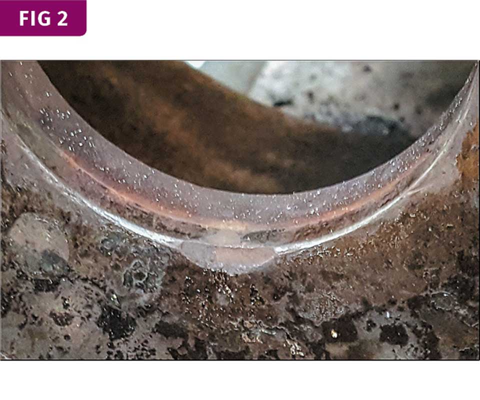
Note the damage to the bottom of the platen alignment hole due to a tilted mold.
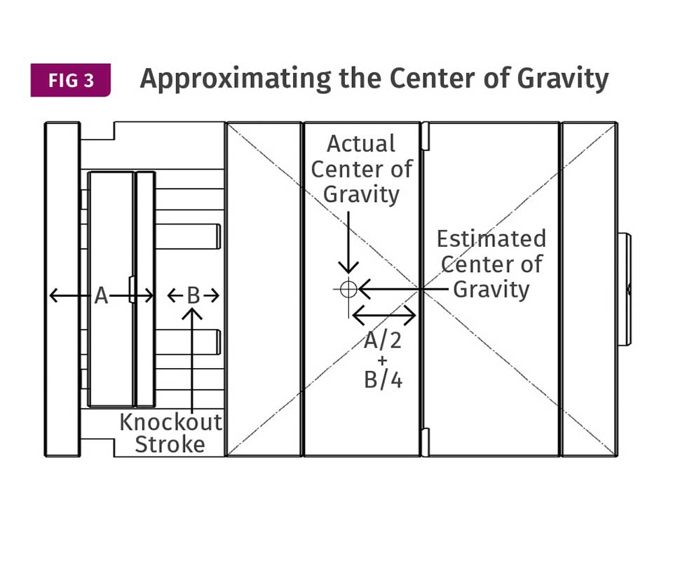
If your CAD program cannot specify the center of gravity, you can estimate one by drawing a set of intersecting lines from the corners of the top clamp plate and the B-Retainer plate. Draw a horizontal line from their intersection point toward the ejector housing. The center of gravity will be approximately one-half the thickness of the rear clamp plate and ejector plates, plus one quarter the ejector stroke, away from this intersection point.
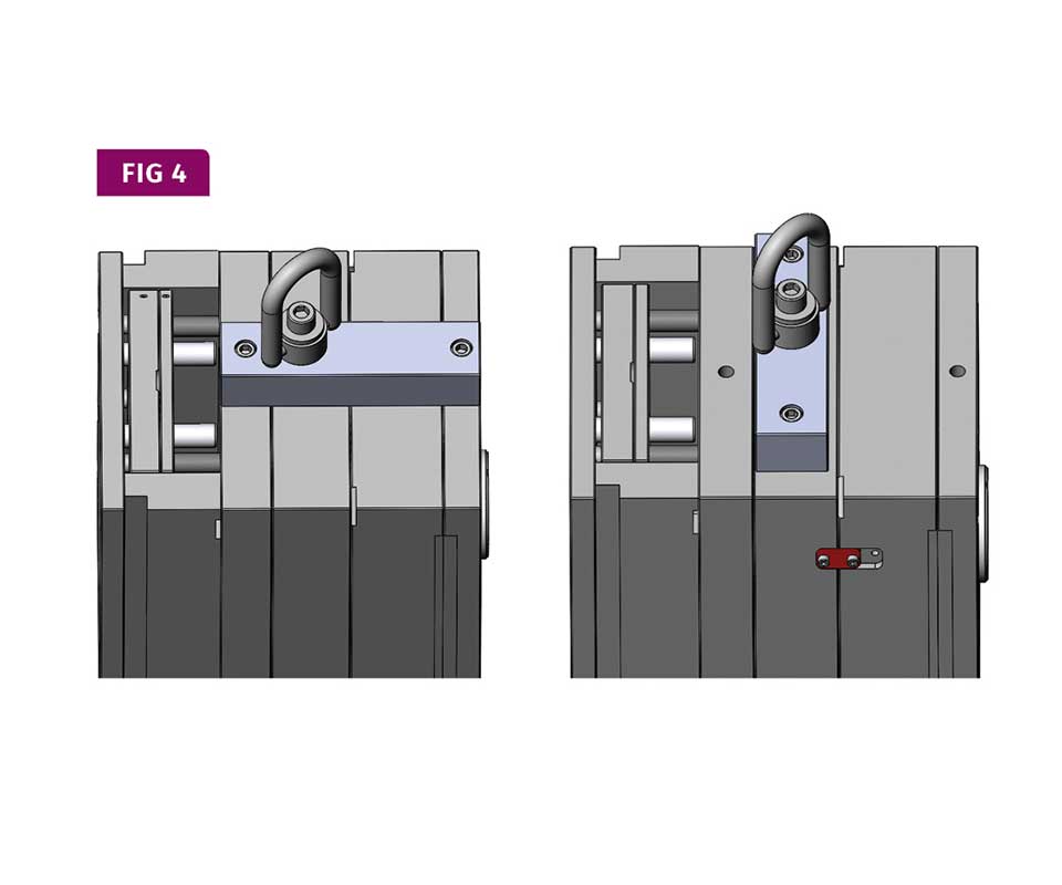
The best lifting bar is mounted parallel with the mold’s centerline and has at least two bolts keeping the mold halves together. A lifting bar mounted perpendicular to the mold’s centerline will also work if the mold has a safety strap preventing the two halves from separating.


Parts 1 and 2 of this column in March and April reviewed the various types of locating rings available and their physical characteristics. This month I will explain how the type of locating ring and the mold design can help reduce damage to the platens and provide a number of other benefits.
How far should a locating ring extend beyond the face of a mold in order to make setups easier and reduce potential damage to the platen? That depends on how long and how level the mold is when suspended by the crane. The longer the mold and the more it is tilted, the more lead-in is required to prevent the top or bottom edges of the mold from hitting the platen before the locating ring does (see Fig.1). The accompanying table shows it doesn’t take much of an angle for potential damage to occur.
But most setup men prefer a mold that has a slight tilt backwards, or counter-clockwise as viewed from the operator side of the machine. This small angle puts the bottom edge of the locating ring up against the platen. As the mold is lowered slowly into the machine, the locating ring will automatically slip into the hole in the platen. Unfortunately, if the mold is heavy, or if the lowering speed is somewhat fast, there is a strong likelihood of damaging the bottom edge of the platen alignment hole (Fig. 2).
Some molders understand this and prefer that the mold has a slight tilt forward. In this case, the top edge of the locating ring is up against the platen and it too will slip into the alignment hole. The problem with this configuration is that if the mold doesn’t have a safety strap, there’s a chance the A-plate will slide out of the B-plate and fall to the ground.
Actually, a tilt in either direction can be a safety hazard. When you open the safety gate to install the mold clamps, if the moving platen on a hydraulic machine is not under pressure, it can be pushed open by either the top or bottom edge of an unbalanced mold.
From a design standpoint, there isn’t much you can—or would want to—do about the length of the mold. The obvious solution is to have an eyebolt hole at the mold’s center of gravity to ensure the mold is level when lifted into the machine. First check with the molder to verify what he or she considers the top of the mold should be. The orientation may vary depending on whether the plan is to use top-entry robotics, or manual part removal from the side.
Obviously, the best scenario is to have eyebolt holes at the mold’s center of gravity on all four sides. It is also advantageous to put an eyebolt hole at the center of gravity on each mold half. This is especially important with large molds. Assembling a large mold on the bench or hanging it one half at a time in a machine can be a difficult, if not dangerous, task. It is even worse if the mold is dangling on an angle, which can result in mold damage, platen damage, or pinched fingers.
It’s good practice to stamp all of the eyebolt holes with the diameter of the bolt. It’s understood that eyebolt holes are tapped with a coarse (not a fine) thread (UNC vs. UNF). With so many offshore molds finding their way onto the production floor, bad things can happen when you force a UNC eyebolt into a metric threaded hole—or vice-versa.
Many solid-modeling CAD software programs can accurately specify the location of a mold’s center of gravity with just a couple of mouse clicks. If your CAD program cannot specify the center of gravity, a good approximation can be determined by drawing a set of intersecting lines from the corners of the top clamp plate and the B-Retainer plate (Fig. 3). Draw a horizontal line from their intersection point toward the ejector housing. The center of gravity will be approximately one-half the thickness of the rear clamp plate and ejector plates, plus one quarter of the ejector stroke, away from this intersection point. No matter what method you use to determine the mold’s center of gravity, don’t forget to add a safety strap to prevent the two mold halves from separating.
If you can’t install an eyebolt hole at the center of gravity due to an interlock, water line, or some other obstruction, you can work around the problem by adding a lifting bar. The best lifting bars are parallel with the centerline of the mold and have at least two bolts keeping the mold halves together. This configuration also vertically aligns the two mold halves. It eliminates the unwanted stress on the leader pins, interlocks, shut-offs, cam heels, etc., which is unavoidable when lifting a mold up with an eyebolt in a single plate.
A lifting bar mounted perpendicular to the mold’s centerline will also work if the mold has a safety strap preventing the two halves from separating. Don’t forget to engrave the mold or part number on both the lifting bar and the safety strap. Unmarked lifting bars and safety straps scattered around a molding room are more than just bad house- keeping—they are an accident waiting to happen.
Reducing the amount of time it takes to set up a mold is always on management’s radar. The fastest way to lift a mold is with a single eyebolt, as mentioned in the previous examples. Using two eyebolts and a chain sling is a little slower, but it is the safest. If one eyebolt fails, the other is there for protection. Two chains can also help level the mold, especially if you can adjust the length of the individual chains. The ideal scenario is to have a parallel lifting bar with two eyebolt holes equidistant from the center of gravity.
Regardless of how many eyebolts you use, you cannot allow the mold halves to separate. I’m not sure how much time it takes to comprehend and react to a dangerous situation, but by my calculation, it takes exactly 0.5 sec for a mold or mold half—large or small—to hit the ground from a height of 4 ft.
In many cases, not enough consideration is given to the selection of the type of locating ring, its physical characteristics, and the location of the eyebolt holes. Hopefully this three-part column increased your awareness of their importance. After all, these “minor” mold details can have important effects:
• Reduce the damage to the platen face and alignment orifice.
• Reduce the chance of personal injury.
• Reduce the mold setup time.
• Reduce the chance of “blow-back.”
• Reduce damage to the heater bands.
• Reduce damage to the mold’s parting line.
• Reduce wear on mating mold components.
• Broaden the processing window.
This three-part article is dedicated to my friend and former colleague, Miguel Pinto, who was critically injured while hanging an injection mold.
ABOUT THE AUTHOR: Jim Fattori is a third-generation injection molder with more than 40 years of molding experience. He is the founder of Injection Mold Consulting LLC, and is also a project engineer for a large, multi-plant molder in New Jersey. Contact jim@injectionmoldconsulting.com; injectionmoldconsulting.com.
Related Content

Back to Basics on Mold Venting (Part 2: Shape, Dimensions, Details)
Here’s how to get the most out of your stationary mold vents.
Read More
Why Shoulder Bolts Are Too Important to Ignore (Part 2)
Follow these tips and tricks for a better design.
Read More
Where and How to Vent Injection Molds: Part 3
Questioning several “rules of thumb” about venting injection molds.
Read More
Hot Runners: A View from the Bottom Up
Addressing hot-runner benefits, improvements, and everyday issues from the perspective of decades of experience with probably every brand on the market. Part 1 of 2.
Read MoreRead Next

Locating Rings and Platen Damage: Part 2
Selecting the right locating ring and putting it to good use takes careful consideration.
Read More
What You Need to Know About Locating Rings: Part 1
Selecting the right locating ring and putting it to good use takes a lot of thought.
Read More
Troubleshooting Screw and Barrel Wear in Extrusion
Extruder screws and barrels will wear over time. If you are seeing a reduction in specific rate and higher discharge temperatures, wear is the likely culprit.
Read More