
Sizing the Barrier Gap
Here’s a less complex way to properly size the barrier gap for barrier screws.
.jpg;width=70;height=70;mode=crop;format=webp)
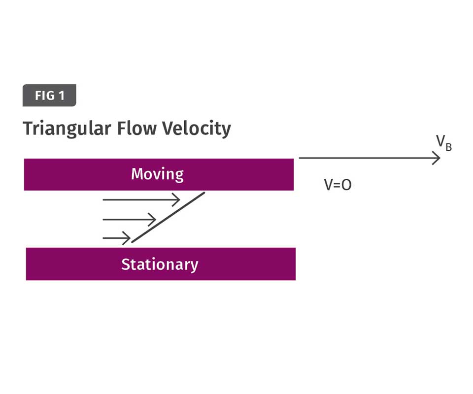
Drag-flow velocity with a moving plate (barrel) against a stationary plate (screw flight) is triangular. The polymer at the stationary plate represents zero and the moving plate Vb.
If you can calculate the output of the screw and how much of that is designed to go over the barrier, you can use drag flow between parallel plates to approximate the length of the barrier gap.


I’ve come across a variety of barrier gaps on barrier screws that are seemingly unrelated to the melting-section design. If done properly, the barrier length automatically becomes a function of the designer’s choice for the melting area and its resulting length.
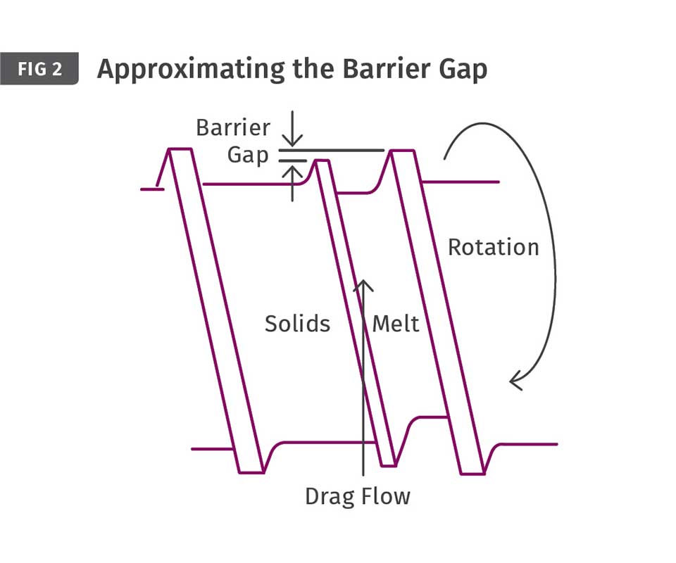
The melt flow over the barrier gap is controlled by the melting rate, which is a complex calculation. In general, the barrier clearance should be greater than the thickness of the melt film, so that all the melt can pass over the barrier flight with the natural drag flow. A gap that’s too restrictive will cause accumulation of melt in the solids channel and end up decreasing the melting rate. Conversely, a gap that’s too large could allow passage of unmelted polymer to pass into the melt channel, where it’s more difficult to melt.
The barrier clearance is typically measured from the O.D. of the screw flights, as the film between the main flight and barrel wall is assumed to remain static. According to the 1970 textbook published by Van Nostrand Reinhold Co., Engineering Principles of Plasticating Extrusion, by Zehev Tadmor and Imrich Klein, the film thickness during melting in the solids channel can be represented by:
δ ={[2K(Tb-Ts)+μVj2]x / Vbx ρ[Cs(TM-TB) + λ]X }1/2
Trouble is, some of these values are constantly changing and are difficult to obtain over the entire length of the melting area, such as (μ) the viscosity at the interface of the film and the solid; (Ts) the temperature of the solid under the film; and (TM) the temperature of the melt in the film. Additionally, the surface area over the solids in the channel (X), the rate of compression, and the flight pitch can change, affecting the melt-film formation. It’s difficult to make even an average estimate of some of the values because of their constantly changing nature. The other values in the melt-film calculation are all known or can be calculated from the screw geometry, screw rpm, and barrel temperatures.
So from an expeditious point of view, what can be done to size the barrier gap without having to deal with the complex calculations for the thickness of the melt film? Well, if you can calculate the output of the screw and how much of that amount is designed to go over the barrier, you can use drag flow between parallel plates to approximate barrier-gap size. (Keep in mind that many barrier screws allow a portion of the polymer to pass through the solids channel without going over the barrier.) The calculation is:
QD=(WHV)/2
Where:
QD= The portion of the polymer to pass over the barrier (in.3/sec)
W= Axial length of barrier (in.)
H= Barrier gap from barrel I.D. (in.)
V= Peripheral velocity of screw (in./sec)
That makes the equation for sizing the barrier gap as:
H=2QD/WV
The expression in the first equation is divided by two because the drag-flow velocity with a moving plate (barrel) against a stationary plate (screw flight) is triangular in shape, with the polymer at the stationary plate being zero and the moving plate VB (see Fig. 1).
Several factors can affect the flow over the barrier flight in addition to drag flow. First is the pressure difference between the solids and melt channels, but that is generally positive and assists the flow. Also to consider: radial movement of the screw in the barrel and non-uniformity of melt-film formation due to the screw design. Consequently it’s a good idea to allow for those possibilities by oversizing the gap. The width of the barrier flight has minimal effect on the flow of polymer over the barrier. Experience has shown that twice the calculated value is a good choice, and further increases do not show an improvement.
This is not a rigorous solution but works well for barrier screw design and saves a lot of time.
ABOUT THE AUTHOR: Jim Frankland is a mechanical engineer who has been involved in all types of extrusion processing for more than 40 years. He is now president of Frankland Plastics Consulting, LLC. Contact jim.frankland@comcast.net or (724)651-9196.


Related Content

Improve Quality & Productivity With Advanced Screw Design
Most molders are still running with screw designs that haven’t changed much in 30 years. But they don’t need to.
Read More
Improve Production Rates Via Screw Design — Barrier vs. General Purpose vs. Melt Uniformity
I’m looking for a few good molders to help trial a new screw design, and share data and results for a future article to prove the benefits of a melt uniformity screw.
Read More
How Screw Design Can Boost Output of Single-Screw Extruders
Optimizing screw design for a lower discharge temperature has been shown to significantly increase output rate.
Read More
How Much L/D Do You Really Need?
Just like selecting the extruder size and drive combination, the L/D should be carefully evaluated.
Read MoreRead Next

Which Barrier Screw for You?
It depends ... mostly on the melting requirements of the polymer.
Read More
Understanding Melting in Single-Screw Extruders
You can better visualize the melting process by “flipping” the observation point so that the barrel appears to be turning clockwise around a stationary screw.
Read More
Advanced Recycling: Beyond Pyrolysis
Consumer-product brand owners increasingly see advanced chemical recycling as a necessary complement to mechanical recycling if they are to meet ambitious goals for a circular economy in the next decade. Dozens of technology providers are developing new technologies to overcome the limitations of existing pyrolysis methods and to commercialize various alternative approaches to chemical recycling of plastics.
Read More