Clamp Tonnage: More Is Better...Right?
Determining the correct tonnage provides a foundation that must be rock-solid to avoid flash and damage. But applying excessive force can create problems with the part, mold, and machine.
Material selected for this lid was a low-viscosity LDPE, indicating that the pressure required from the injection unit to pack the part would be fairly low.

Melt viscosity is related to clamp-tonnage requirements, but MFI does not reliably correspond to actual melt viscosity in molding and cannot be compared accurately between resin types. For example, PC will always show high viscosity in molding, regardless of whether the MFI is 2 or 25 g/10 min. Also note than an MFI of 10 g/10 min for PP does not mean an equal molding viscosity for the same MFI with PC.

This mold was clamped at four times the required tonnage, resulting in separation of the cavity block in two locations.
Several factors contributed to the frame rails breaking on this vertical press. The mold required about 10 tons to be held shut against the forces of injection, but the clamp tonnage was set to 100 tons.


Many factors must be considered to determine if an injection molding machine has the capability to mold parts on a consistent basis. The injection unit must have the correct shot volume to avoid degradation and unmelt. It must also have pressure in abundance and a flow rate high enough to allow for proper part filling.
Plastic variables also must be considered, focusing on how important it is to process from “the plastic’s point of view.” It’s important to dry the material to appropriate moisture content, process within the recommended melt temperature, select the correct flow rate for injection, apply adequate hold time and pressure, and cool long enough to maintain dimensional stability. However, these variables only focus on the injection aspect of the process. The clamp end of the machine is responsible for providing force to counter the pressure that is applied from the injection unit. How much tonnage is applied, location of that force, type of clamping mechanism, and size of the mold base all affect the success of the molding process. Determining the correct tonnage is not a simple task. It provides a foundation that must be rock- solid to avoid flash and mold damage. Is it possible to apply too much clamp force, narrowing the process window before molten material is ever injected?
In the following examples, we will focus on using a Decoupled Molding II processing strategy. During the process, the filling of the cavity is separate from the pack/hold phase. The filling stage should yield a part that is 95% to 98% visually full, resulting in zero pressure at the end of the mold cavity.
As the machine transfers from velocity to pressure control for the pack/hold phase, the cavity becomes visually full. Additional material is packed into the cavity to minimize sinks and decrease dimensional variation. Inside the cavity, the pressure increases, so the clamp must provide enough force to overcome the pressure applied in the cavity.
DETERMINING CLAMP TONNAGE
The starting point for determining appropriate clamp tonnage is to calculate the projected area of a single part. Then any cored-out surface area shall be removed from the overall surface area of the single part. Once the total surface area of the part is determined, we must multiply it by the number of cavities in the mold. If the mold has a cold runner, its entire surface area must be taken into consideration as well.
After obtaining the total projected area of all parts plus the cold runner, we must then multiply that area by a tonnage factor. Tonnage factors used to be found on the material specification sheets, but nowadays that information rarely finds its way onto those data sheets. Typical tonnage factors can range from 2 to 10 tons/in.2, but for a starting point we recommend 3 tons/in.2.
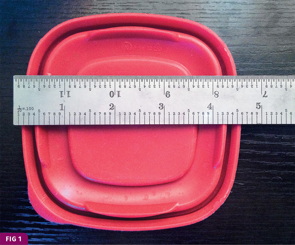
As an example, let’s propose molding a lid for a square leftover dish (Fig. 1) with a hot-runner mold and eight cavities:
Cavity Area = length × width = 4.6 in × 4.6 in = 21.16 in.2
Parts Area = cavity area × cavities = 21.16 in.2 × 8 = 169.28 in.2
Tonnage =parts area × tonnage factor = 169.28 in.2 × 3 tons/in.2 = 507.84 tons
Now we have a starting point to determine what clamp tonnage is correct for this mold. But other factors must also be taken into consideration to determine if the tonnage required will be above or below 3 tons/in.2.
• Melt flow index or rate (MFI, MFR);
• Flow length;
• Wall thickness;
• Gate location;
• Gate size;
• Number of gates;
• Volume of resin.
The first item that needs to be considered after calculating the tonnage based on projected area is how the material flows. MFI or MFR can be found on the material data sheet from the supplier. A material with a high MFI or MFR will require less pressure from the injection unit to complete the packing phase; therefore, the tonnage required will be lower.
When evaluating the MFI or MFR, it is imperative that a comparison be done only between grades of the same type of resin. The reason for this is the ASTM test has a different temperature, orifice size, and weight for each type of resin. These values do not correlate directly with molding, because of how the ASTM test is performed and how molding machines actually operate. The MFR or MFI relate more closely to the packing phase since it is typically at a much lower flow rate than the filling phase (see Fig. 2).
When reviewing our example of molding a lid, the material selected was LDPE. This material will likely have a very low viscosity, indicating that the pressure required from the injection unit to pack the part will be fairly low. Therefore, based on material selection, the tonnage required will likely be less than the typical 3 tons/in.2.
Next, we need to evaluate both the flow length and the wall thickness. This is referred to as the aspect ratio, comparing the flow length (from gate to end of fill) to wall thickness. Generally speaking, an aspect ratio less than 150:1 has a low risk of sinks, short shots, or dimensional issues. In our example of molding a lid, the flow length is 3.00 in. and wall thickness is 0.100 in.:
Aspect Ratio = flow length/wall thickness = 3.00/0.100 in. = 30:1
With a very low aspect ratio, the required pressure to pack this part will lower, thus further reducing the required clamp tonnage to hold the mold closed. In addition to lower tonnage, the probability of molding sinks, short shots, or out-of-tolerance parts is reduced.
Next, we need to evaluate the gate size as well as the number of gates. A larger gate diameter has a much larger area for material to flow through, thus requiring less pressure from the injection unit to fill and pack the part. The number of gates will affect the injection pressure during both filling and packing. If there is a greater number of gates, a larger gate area, or if sequential filling requires less injection pressure, the result is a lower required tonnage.
Our example of an LDPE lid has a single gate with a diameter of 0.030 in.
Gate Area = diameter x diameter × 0.7584 = 0.030 × 0.030 x 0.7854 = 0.0007 in.2
This is a very small surface area to inject 23 g of material per cavity. Given this amount of mate- rial and the gate size, expect the injection pressure during the packing phase to be slightly higher and therefore the tonnage requirements would be a little greater than 3 tons/in.2.
Ultimately, the best method to determine required tonnage is to run a simulation with correct geometry, characterized material, and full runner system. Without simulation, we can draw conclusions from evaluating part geometry, material selection, gate size, gate location, and gate quantity. Based on these factors, an expected range for this mold would most likely be 339 to 508 tons (at 2 to 3 tons/in.2). A good starting point would be 420 tons of clamp force.
EFFECTS OF TOO MUCH TONNAGE
Now that we have focused on how to determine appropriate clamp tonnage, let’s take a look at the effects of applying excessive tonnage. Here are some typical molding defects that can be seen on parts almost immediately when tonnage is too high:
- Burns;
- Short shots;
- Gloss level changes
Part quality is not the only item affected when excessive clamp tonnage is applied. There are long-term effects from over- clamping that will damage the mold and machine. First let’s review several of the side effects on the mold:
• Crushed vents;
• Rolled parting line;
• Broken inserts;
• Cracked core or cavity block.
Figure 3 is an example of a mold that was clamped at four times the required tonnage. Based on surface area, material, and gating, the mold required roughly 100 tons (at 3 tons/in.2). The molder was inexperienced and set the clamp tonnage to the machine maximum of 400 tons (12 tons/in.2). Despite a robust mold design, quality steel, proper machining, and correct heat treating, the result of excessive tonnage was that the cavity block separated in two locations. Each split ran the entire depth of the cavity block (roughly 10 in.) from parting line to clamp plate. This was a catastrophic failure that caused delays in production and upwards of $100,000 to expedite the manufacturing of a new cavity block.
Here are some potential failures on the molding machine when excessive clamp force is applied:
- Cracked hydraulic-cylinder mounting plates;
- Deformed platens;
- Fractured machine frame.
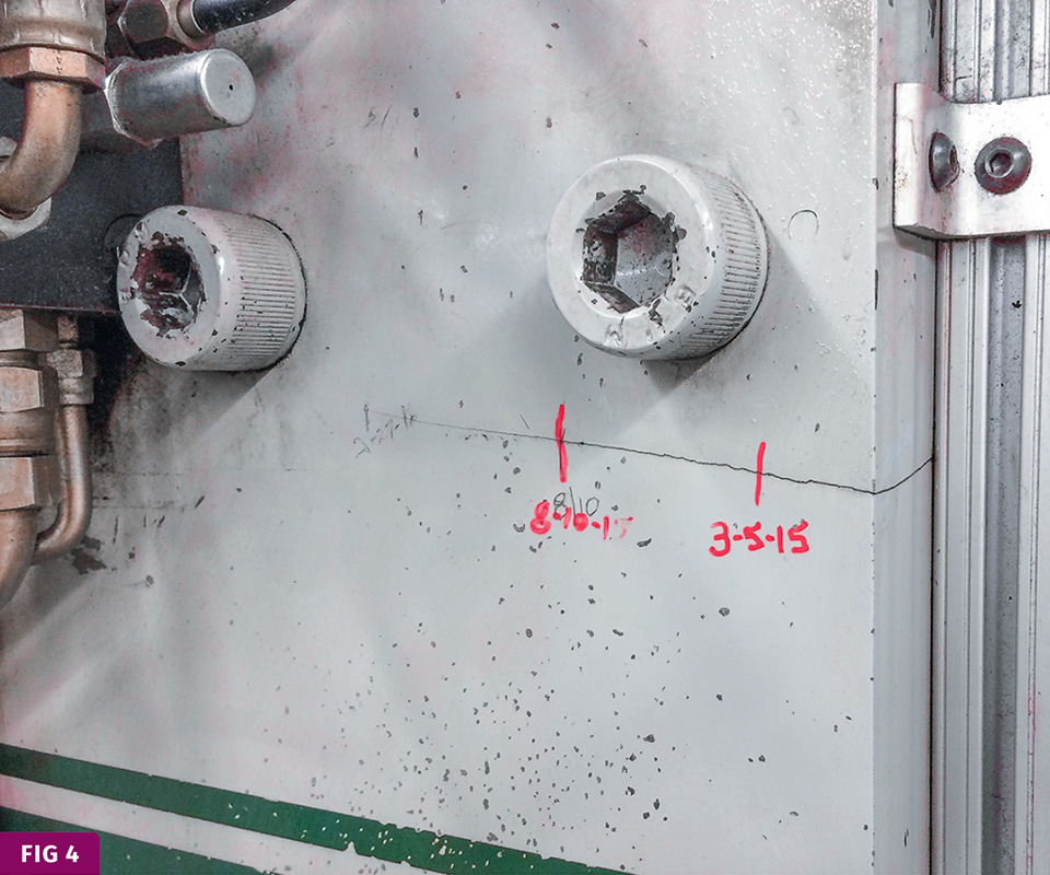
In Fig. 4, there were several contributing factors that caused the frame rails to break on this vertical C-clamp molding machine. First, the mold required about 10 tons to be held shut against the forces of injection, but the clamp tonnage was set to 100 tons. Second the mold-base size covered less than two-thirds of the platen in both direc- tions. Combining these two poor practices over years not only fractured the machine rails, but caused molding defects and mold failure. No one was sure when the failure occurred on the machine, but they did identify when it was first discovered and documented its progression over time. Replacing both machine rails cost thousands of dollars for materials alone. If we factored in the labor hours to disassemble and reassemble nearly the entire machine, and the scrap produced over the years before the rails failed, the number could easily exceed $200,000.
ABOUT THE AUTHOR: Jeremy Williams has more than 16 years’ experience in the plastics industry serving the medical, automotive, furniture, and appliance industries. He previously worked as a principal engineer, taking projects from design concept to saleable products. Jeremy earned his Master Molder II certification in 2011, became an RJG Certified Trainer in 2012, and started at RJG Inc., Traverse City, Mich. in 2016. In addition to his extensive manufacturing background, he holds degrees in plastics and business. Contact 231-947-3111; jeremy.williams@rjginc.com; rjginc.com.
Related Content

Are Your Sprue or Parts Sticking? Here Are Some Solutions
When a sprue or part sticks, the result of trying to unstick it is often more scratches or undercuts, making the problem worse and the fix more costly. Here’s how to set up a proper procedure for this sticky wicket.
Read More
How to Set Barrel Zone Temps in Injection Molding
Start by picking a target melt temperature, and double-check data sheets for the resin supplier’s recommendations. Now for the rest...
Read More
Improve Quality & Productivity With Advanced Screw Design
Most molders are still running with screw designs that haven’t changed much in 30 years. But they don’t need to.
Read MoreRead Next

INJECTION MOLDING: How to Specify an Injection Molding Machine
There are 51 things to consider when spec’ing a controller.
Read More
How Polymer Melts in Single-Screw Extruders
Understanding how polymer melts in a single-screw extruder could help you optimize your screw design to eliminate defect-causing solid polymer fragments.
Read More
Lead the Conversation, Change the Conversation
Coverage of single-use plastics can be both misleading and demoralizing. Here are 10 tips for changing the perception of the plastics industry at your company and in your community.
Read More