
TOOLING: Venting: A View From the Trenches
Venting is a prime culprit for molding problems, partly because toolmakers and process techs have different ideas of what’s needed.
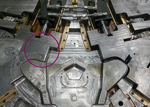
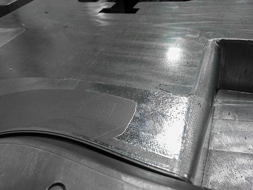
Close-up of circled area on this mold shows coining that resulted from lack of sufficient parting-line bearing surface.
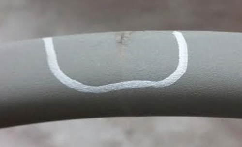
This 33% glass-filled nylon part shows burning (circled) at the knit line because there was no parting-line vent. Sometimes these defects show up over time. That’s why the author advises peripheral venting with open vents and bearing surface to support them.


I’ve been holding off on broaching this subject for a while, even though it’s one I have devoted a lot of time and attention to and one that I have strong opinions about. With this topic, I may do some finger-pointing at others who have strong opinions, versus real-world data. I will always back up what I write with data or factual experience, and I won’t state something as fact if it is a theory, assumption, or opinion.
If you have been reading my column you know that I spent the first half of my career building and designing injection molds. During that time I was focused on building the highest quality tool for producing a clean part. I had high criteria on how my tools were built, never sacrificing quality. But at that time I had no idea how the tool could affect the process window on the molding side, and I found out later that I had some big gaps in my tool standards. So I am at liberty to talk to tool shops and tool makers about their opinions on venting and how some standards they are using cause issues on the molding floor.


When I moved to the molding side in early 2002, I thought I was ready for what lay ahead with my experience from the tool-shop side. It didn’t take long to realize the adventures I was in for. But because I kept an open mind, I learned that my previous standards for building tools were not what the industry needed. And with managing over 8000 preventive-maintenance (PM) procedures and repairs a year, we could prove out results over time on numerous tools. Now let’s get back to this month’s topic.
VENTING IS NUMBER ONE
Venting, out of numerous issues in my arena, is the number one issue we deal with daily concerning part quality and processing. Back in early 2002, we would just open up the existing vent design or add vents where needed. At the time, I had no idea how the land and width and depth of the vent could have an impact. I will always remember the time a material rep came in to address a part quality issue we were experiencing. I wish I remembered his name, he opened my eyes.
His suggestion was to add a vent along the problem area, 2-3 in. long with a 0.030-in. land. I was a little surprised, thinking that was pretty close to the cavity, with the vent relief being only 0.030 in. away. I had never made a vent wider than the cutter width. But I had no reason to say no because I had no data or experience to say otherwise. So we went ahead and modified the vents like he suggested. It did not solve the problem we were having, but venting was now off the list of possible solutions. And it opened my mind to venting as a possible solution for future problems. I like to bring this example up because it was the one that began to change the standard I was taught from working in the tool shops.
Inadequate venting on the mold can create many issues: weak knit lines, gloss variations, bubbles, splay, burns, erosion, increased cycle time, excessive cleaning of the parting lines, and very small process windows when lack of venting is “processed around.”
What is adequate venting? That depends on who you talk to; there are so many opinions on venting, and most, I found, are pure opinion based on lack of true knowledge or experience. One thing that has always bothered me is how tool shops have affected standard practice. A tool can go out to add or deepen vents, come back, and now the part has flash. The assumption is that we can’t have that, so the tool goes back out and comes back making burns on the part. I’ve seen this so many times, it can be frustrating.
Vent land length and depth are critical in problem areas, and many variables affect the correct solution: plastic material, flow length, wall stock, and part geometry. There are standards for vent depths with specific materials but these are just averages for perfect conditions. For example, with PC/ABS, I have had parts where I could go 0.002 in. deep in vents with no flash concerns. With the same material on a different part, vents could go only 0.0007 in. deep. Those parts and processes were completely different in geometry and fill pressures. I have had vents flash and people assumed the vents were too deep, when the root cause was actually tool deflection with lack of preload on the support pillars.
How vents are added can affect the molding results. I prefer to machine or surface grind vents whenever possible, but vents often need to be ground in by hand by a toolmaker because of the parting-line geometry. With every toolmaker, the result will be different, according to his skill and technique. I have seen many occasions where a vent has flash but is not open all the way—open at the cavity and closed off by the relief. It took me years to learn a proper technique whereby I know how deep the vent is when hand grinding. I use a specific brush trimmed to a specific length and will only use one brand of spotting blue. Yes, that probably sounds pretty fussy, but remember the case I mentioned above about tool shops going from flash to burns? I’ve corrected hundreds of those issues.
PARTING-LINES & VENTING
One other area that impacts venting is parting-line bearing surface. With too much relief and not enough bearing surface, your vents will close off. This is one standard I have changed since moving to the molding side. Back when I was building tools, I thought less bearing surface with plenty of parting-line relief was the correct approach. Years ago, that was needed to help spot the tools down; but with today’s technology, if any tool shop says they need relief to help spot, I just smile.
It’s an old standard and people are starting to understand the negative impact too much parting-line relief can have. It’s about tonnage per square inch: The more bearing surface you have will keep your vents open longer. I have actually seen a tool that was coined in 0.025 in. over the years from lack of bearing surface. And more bearing has nothing to do with flash concerns. Flash is about plastic/cavity pressure overcoming clamp pressure. Bearing surface is not part of the formula.
I took a long lead-in for this topic to address how opinions can be formed about venting. In my next column I will get into details on proper vent design, discussing parting lines, runners, core pins, ejector pins, blind inserts, slides, and lifters.


Related Content

How to Start a Hot-Runner Mold That Has No Tip Insulators
Here's a method to assist with efficient dark-to-light color changes on hot-runner systems that are hot-tipped.
Read More
Hot Runners: Truths. Myths, Overlooked Areas: Part 2
Here’s a view from the trenches of a tooling manager who, over 30 years, has experienced the joys and pains of using virtually every type of hot runner on the market. Part 2.
Read More
How Do You Estimate Cycle Time?
Molders price jobs based on estimated press time, and that is where you can either be very profitable or lose your shirt. But there’s a new, free resource to help you out.
Read More
How to Select the Right Tool Steel for Mold Cavities
With cavity steel or alloy selection there are many variables that can dictate the best option.
Read MoreRead Next

How Polymer Melts in Single-Screw Extruders
Understanding how polymer melts in a single-screw extruder could help you optimize your screw design to eliminate defect-causing solid polymer fragments.
Read More
Advanced Recycling: Beyond Pyrolysis
Consumer-product brand owners increasingly see advanced chemical recycling as a necessary complement to mechanical recycling if they are to meet ambitious goals for a circular economy in the next decade. Dozens of technology providers are developing new technologies to overcome the limitations of existing pyrolysis methods and to commercialize various alternative approaches to chemical recycling of plastics.
Read More
People 4.0 – How to Get Buy-In from Your Staff for Industry 4.0 Systems
Implementing a production monitoring system as the foundation of a ‘smart factory’ is about integrating people with new technology as much as it is about integrating machines and computers. Here are tips from a company that has gone through the process.
Read More