
TOOLING: Venting: Where And How Deep?
After last month’s introduction to the subject, let’s get into the details on vent depths, land lengths, and the alternatives to perimeter venting.
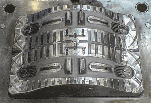
This picture shows the old industry standard with single vent tracks spaced out around the part. These take away too much parting-line bearing surface and have too much vent land.
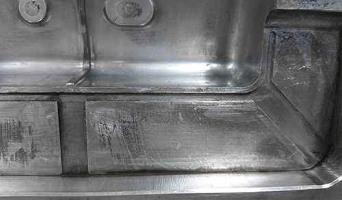
This picture shows a vent track cut along the edge of the part with a thin land that provides better venting.


In this column we will get into more specifics and details on venting. Let’s start with the most common type, parting-line vents. The old standard for parting-line vent design was to take a cutter, typically 0.250 to 0.500 in., and cut the relief of the vent to within 0.250 in. of the cavity. Typically a vent would be cut every 1.5 to 3 in. apart around the perimeter of the cavity (see detail). Relief channel depth can vary, depending on opinion. I have found that 0.010 to 0.015 in. is adequate in most cases. (At times this can be deeper for certain materials and for overflows, as discussed below.)
Shortly after moving from the tool shop to the molding side, I realized that the standards just cited were not the best and caused issues with inadequate venting. Two things were really the culprit, the vent land length and too much removal of parting-line bearing surface, with the number of vent relief channels contributing to coining of the parting lines and closing off the vents. I will get into better vent relief designs shortly.


The distance of the relief from the cavity is the length of the vent land. With the old standard, the land length would vary with the radius of the cutter. The longer the vent land, the quicker the vents can plug up from outgassing residue. So vent land length can be a contributor to venting problems.
Vent depth is a factor that many fail to take the time to understand when they are dealing with issues of burns versus flash, as I mentioned in last month’s column. There are material specs for vent depths, but they are specs for the standard scenario.
Depending on the process, part geometry, and pressures, the vent depths can be deeper than the spec or may have to be shallower.
So what is a better design for relief of parting-line vents, and how thin can we go with vent land (or how close can we cut the relief to the cavity)? This is where many strong opinions can come in, and I smile when some are folks are so firm on their opinions, though they actually live their life behind a desk and not in the trenches. Over the years, when venting was on the list of possible root causes for a molding issue, I always wanted to take it off the list right away rather than make continual adjustments. I called it “maximized venting,” so when I was done modifying the vents it was, for the most part, off the list of potential problem causes. With this mentality, and through dealing with thousands of molds, I learned a lot about venting and its long-term impact on mold maintenance.
PERIMETER VENTING OR NOT?
You can drastically increase your volume of venting and reduce the amount of parting-line bearing surface, depending how you design and cut your relief channels. The width of the track does not impact the amount of venting you have. I prefer to run smaller tracks along the cavity edges and then T-off with the relief to atmosphere at knit lines, corners, dead ends, and end-off-fill areas.
It seems like it’s 50/50 in the industry concerning who is for perimeter venting and who is not. I personally do not have any objection to it, but I understand it is not a necessity. There is absolutely no disadvantage to perimeter venting, and only advantages if the relief channels are designed correctly.
My starting point typically is a 0.080-in. land along the edge of the cavity, 1 to 3 in. long, unless going with perimeter venting. When there is a venting issue that is still causing a problem, I will shorten my land to 0.030-0.040 in. Some are thinking that’s way too close to the cavity; it will erode or get damaged. I use to think the same thing, but I found the opposite was true. I have had numerous cases of erosion from lack of venting at critical parting-line edges and resolved to defeat the erosion issue with improved venting. This was usually with a PC/ABS material at knit lines and high fill pressures from thin walls in the part.
In some cases I have eliminated splay issues with perimeter venting, and then observed the splay coming back when the vents coined shut from lack of parting-line bearing surface. Then we opened the vents back up and the splay was gone, like turning off a light switch. On another occasion we had splay coming off some rib details near the end of the part. The tooling engineer and process technician asked me to open up the vents on the end of the part. I told them sure, but didn’t think it would have any impact on the splay issue. Typically we would end up venting the ribs to try to resolve this.
We opened up the vent track that was cut in along the whole end of the part, and amazingly, the splay disappeared. That is why, when it comes to venting being a possibility to resolve an issue, I always make sure that the venting is adequate because it is one of the easiest things to take off the list of possible causes.
HOW DEEP THE VENTS?
Vent depth has many variables, so you will need to understand this before you think you are at maximum depth. In cases where venting is very critical to the process and part quality, I actually keep going deeper until I create flash and then weld it back up to the point where flashing stops. I do that when the payback is there, and with internal resources, repairing the flash was quick and cheap. As pointed out in last month’s article, you also need to take tool deflection into account from lack of support or preload whenever you are dealing with flash, even on vents.
While we are on the topic of parting-line venting, let’s discuss the one situation, which is material specific, where I go beyond the standard no-flash venting. When running large glass-filled nylon parts, knit lines or end-of-fill areas can experience problems with buildup of volatile deposits and resulting part-quality issues. In the rare cases where constant cleaning is necessary to make a good part, I tend to go with an overflow tab. Vents are just deep enough to fill the overflow pocket and are tapered to the edge of the part to break clean on removal to avoid vestige. In most of the thousands of venting issues I have seen, there is a sweet spot between burns and flash. You just need to take the effort to find it.
I personally would never try to process around a venting issue: You are at risk for part-quality issues and can force yourself into a small process window. Many in the industry will use tape or paper on the parting lines or back off clamp tonnage to address venting issues. But if you are able to correct the issue, then you can resolve it with proper venting at the proper depth. Open is open, whether it’s from the tape or breathing from reduced clamp tonnage. Tape will not last long, and if you are able to run with less clamp tonnage then other questions come to mind. If you have proper venting area and depth, along with adequate parting-line bearing surface, that is the most robust solution.
One more thing: Cold runners should always be vented to the point of almost flashing. I have seen where venting of the runner alone has eliminated splay issues through gates.
Next month I will get into some details on venting components such as ejector pins, core pins, slides, lifters, blind inserts, and part details that can cause venting issues. I will also touch on a rare occasion where we created a Venturi effect with venting on a part detail that had the opposite effect of venting. But it also proved that a blind pocket not exposed to atmosphere can still assist with venting.


Related Content

How to Stop Flash
Flashing of a part can occur for several reasons—from variations in the process or material to tooling trouble.
Read More
How to Get Rid of Bubbles in Injection Molding
First find out if they are the result of trapped gas or a vacuum void. Then follow these steps to get rid of them.
Read More
The Importance of Melt & Mold Temperature
Molders should realize how significantly process conditions can influence the final properties of the part.
Read More
Tunnel Gates for Mold Designers, Part 1
Of all the gate types, tunnel gates are the most misunderstood. Here’s what you need to know to choose the best design for your application.
Read MoreRead Next

TOOLING: Venting: A View From the Trenches
Venting is a prime culprit for molding problems, partly because toolmakers and process techs have different ideas of what’s needed.
Read More
Processor Turns to AI to Help Keep Machines Humming
At captive processor McConkey, a new generation of artificial intelligence models, highlighted by ChatGPT, is helping it wade through the shortage of skilled labor and keep its production lines churning out good parts.
Read More
Advanced Recycling: Beyond Pyrolysis
Consumer-product brand owners increasingly see advanced chemical recycling as a necessary complement to mechanical recycling if they are to meet ambitious goals for a circular economy in the next decade. Dozens of technology providers are developing new technologies to overcome the limitations of existing pyrolysis methods and to commercialize various alternative approaches to chemical recycling of plastics.
Read More