A Systematic Approach to Process Development
The path to a no-baby-sitting injection molding process is paved with data and can be found by following certain steps.


A few years ago, I was asked by a company in the Los Angeles area to give a demo of my process-development software, Nautilus. The company’s owner/president was told by his customer to look at the program as a way to aid its process development. He was very upset! I walked in into the conference room, and the first thing he said—even before any greeting—was, “Why should I buy your software, when I have been deve loping processes for years without any tool and have run a successful business?”
I calmly replied, “You are absolutely right! You have run a successful business, but you could have been running an even more successful and profitable business,” which again irritated him. I always lead by example, and so although I was only planning to be there for an hour or so, I spent the rest of the day (at no charge), and took one of his four-cavity molds in production, dropped the cycle time from 32 to 26 sec—a 16% reduction—while also lowering his inspection frequency and developing a no-tweak robust process that they could run “forever” with no process changes.


With all due respect to all the processing personnel of our industry, the biggest mistake I have seen is to try to mold parts to specifications during the first run at the molding shop or at the moldmaker. The first run should focus on two primary aspects.
First, has the mold been designed and built such that the process will be “no-tweak, no baby-sitting required”? Once the mold is in the press and running production, a process technician should never be required until maybe at the end of the run. The second aspect is to check whether the product quality is well within the specification limits and whether the process will need to be constantly adjusted to maintain product quality. For example, will process changes be required when going from the day shift to the night shift or if the shop door is open?
A robust process is one that will produce parts within the required quality specifications without any change to the process parameters throughout the entire production run and future runs. Achieving such a process should be the goal of process development. I start off my seminars asking the class, “If I ask you to drive a car for 5 hr with no stops and the cruise control set at 80 mph, which road do you prefer—the road on the edge of cliff or a wide-lane straight highway?” The class always finds the answer to be obvious.
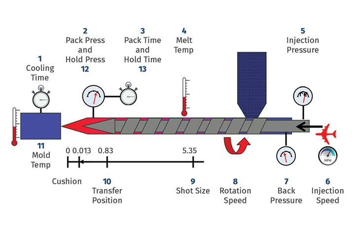
The 11 + 2 injection molding processing parameters.
With the road on the cliff, one small distraction or a slight error can send you careening, but if you’re driving on a wide road you can afford a brief diversion of attention to adjust the temperature inside the car, select a radio station or have a sip of water. In simple terms, that is robustness. The process should be able to cushion in any natural variations and still produce parts within specifications. Natural variations will always be present in every process, whether that process is driving to work from your house, a molding process, or the formation of ice crystals. The goal should be to minimize the variation since it can never be eliminated. A molding process must be able to run in cruise control and must be robust.
Where does the variation come from in the molded product? On a broad scale, the variation can come from the machine, the plastic, the environment, the measurement systems, the personnel, and the molding process. There could be a few more, but these are the primary contributors. As a processor who has a mold in the machine and needs to develop a molding process, we need to focus on the molding process. Of course before that, we need to understand and evaluate the machine, materials, and other inputs that determine that they are all performing adequately with the least amount of variation. These are what I call the 11+2 process parameters on the molding machine that will influence the quality of the part (Fig. 1). If the pack and hold phases are separated, then there are 13 parameters, but in some cases they are not separated and so we have 11 parameters.
These parameters now become a source of variation for part quality and therefore we need to find their optimum settings where the process can be robust. We need to find a wide lane for each parameter so that we will ultimately have a process that will also be molding parts on a wide-lane highway. Processors will often use the techniques of Scientific Molding for process development.
I consider the process to be the complete journey of the pellet, and we need to pay attention to every aspect.
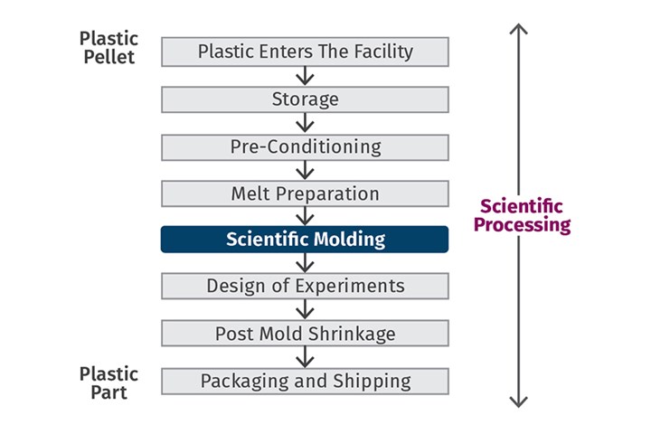
I prefer to use the term Scientific Processing, since the process starts when the plastic pellet comes into the molding shop and is stored, dried, and processed into a part, and then experiences post-mold shrinkage and is packed and shipped out of the door. I consider the process to be the complete journey of the pellet, and we need to pay attention to every aspect. Scientific Molding is the process-development activity we do at the molding machine (Fig. 2).
I split my process-development activity into two phases (Fig. 3). In the first phase, I explore each of the 11+2 parameters, and find the range of settings where cosmetically acceptable parts can be molded. These are called Cosmetic Process Windows (CPW). You can relate the CPW to finding the width of the highway lane where you could drive your car. Most importantly, I do not look at any dimensions during Phase 1. The whole goal of Phase 1 is determining, “Can I have a robust process regardless of the dimension?”
Learn to view scientific molding as one element of scientific processing.
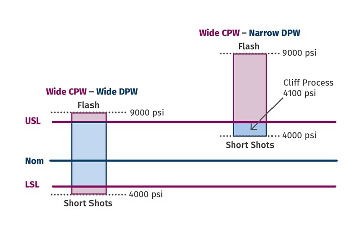
Dimensions must be looked at in Phase 2. Once I know the ranges (process windows) where I can get cosmetically acceptable parts, I will then perform a Designed Experiment (DOE) to evaluate the relationship between the dimensions and the range of each setting. For example, let us consider that below a pack pressure of 4000 plastic psi the parts have short shots, while above 9000 plastic psi, the parts have flash. Therefore, parts molded at 4000 and 9000 psi are cosmetically acceptable and the width of the process window is 5000 psi.
A DOE would mean measuring dimensions at pack pressures of 4000 and 9000 psi and then selecting a pressure between 4000 and 9000 psi to achieve the required dimensions. In fact, this can be a range not just one pressure. For example, we could achieve dimensions between 5500 and 6500 psi. This range is now called at the Dimensional Process Window (DPW). The wider this window, the more robust your process is.
With the 4000 to 9000 psi CPW, if the required minimum pressure to mold parts that meet the required dimension is, for example, 4100 psi, then the process is now at the edge of the cliff (Fig. 4). If the pressure is increased, the parts will go out of spec, and if it is decreased below 4000, the parts will be short. You can mold acceptable parts as long as the pressure is always going to be exactly 4100 psi with absolutely no variation. But we know that is not practical in production, and therefore there will be a risk of short shots and/or parts out of spec being mixed in with acceptable parts. We should always avoid processes on the edge of the cliff for obvious reasons. It is also worth remembering here that the first thing a quality inspector looks for is if the part is cosmetically acceptable. They will only check the dimensions if it is free of cosmetic defects.
So what do we do if the dimensional window is small; if the only pressure we can mold parts to the required dimension is 4100 psi? There are only two choices if you want to have a robust process. I would choose the center point of the pressures as the preferred process. In this case, that would be 6500 psi. The two choices are to change the dimensions of the cavity steel or to change the specifications of the dimensions. You can also have a combination of the two. In most cases changing product specifications is not an option and so we will need to focus on the cavity steel. (Tooling engineers, please read on before you form any opinions.)
The cosmetic process window versus the dimensional process window.
A DOE will consist of using not just one process parameter but at least three to five of the 11+2 that have the biggest influence of the part quality. Think about the Pressure–Volume–Temperature (PVT) diagram for selecting these factors. All changes in steel dimensions and/or product specifications must be data driven and should be based on DOEs. The tooling engineers should be given convincing numerical information based on experimental data to change the cavity steel dimension. Lack of this has been the frustration of tooling engineers. A comprehensive study must be done before making any steel changes. Taking steel off is easy; adding it back, not so much.
Establishing the molding process in two phases will help you make data-driven decisions that lead you to a cruise-control process that will consistently produce acceptable parts. The dimensional process window is always a subset of the cosmetic process window, and so the wider the cosmetic process window the better the chances of a wider dimensional process window and smoother cruise control. I have used this technique successfully for the last 24 years at several companies. Data-driven decisions are the key.
ABOUT THE AUTHOR: Suhas Kulkarni is the founder and president of Fimmtech, San Diego, an injection molding service-oriented firm focusing on Scientific Molding. Fimmtech has developed several custom tools that help molders develop robust processes, and its seminars have trained hundreds of individuals. Kulkarni is an author of the best-selling book, Robust Process Development and Scientific Molding, published by Hanser Publications. Contact: (760) 525–9053; suhas@fimmtech.com; fimmtech.com.
Related Content

Improve The Cooling Performance Of Your Molds
Need to figure out your mold-cooling energy requirements for the various polymers you run? What about sizing cooling circuits so they provide adequate cooling capacity? Learn the tricks of the trade here.
Read More
Know Your Options in Injection Machine Nozzles
Improvements in nozzle design in recent years overcome some of the limitations of previous filter, mixing, and shut-off nozzles.
Read More
How to Optimize Pack & Hold Times for Hot-Runner & Valve-Gated Molds
Applying a scientific method to what is typically a trial-and-error process. Part 2 of 2.
Read More
How to Stop Flash
Flashing of a part can occur for several reasons—from variations in the process or material to tooling trouble.
Read MoreRead Next

Process Capability and the ‘Hesitation Effect’
Understanding the concepts of pack and hold and applying them during process development is critical for molders to achieve consistent part quality.
Read More
Optimizing Pack & Hold Times for Hot-Runner & Valve-Gated Molds
Using scientific procedures will help you put an end to all that time-consuming trial and error. Part 1 of 2.
Read More
Better Molding By Design (and Experiment)
Pairing Design of Experiments (DOE) tenets with the principles of Scientific Molding can point towards a more stable injection process.
Read More