
Achieve Process Transparency with In-Mold Cavity Sensors
Tips and techniques: in-mold sensors
In plastic injection molding, the primary objective is to manufacture dimensionally and structurally consistent parts, independent of the molding machine being used.
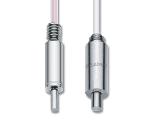
In-mold cavity-temperature and cavity-pressure sensors (left and right, respectively) each have their own merits, but offer powerful benefits when used together.
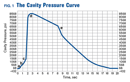
Fig. 1: Typical cavity-pressure curve for a sensor placed near the gate (rather than at the end of fill) shows the switchover/transfer point (c) and gate-seal point (e), among other events in the cycle.
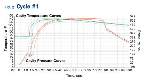
Fig. 2 Curves for a cavity-pressure sensor near the gate and cavity-temperature sensor near the end of fill.
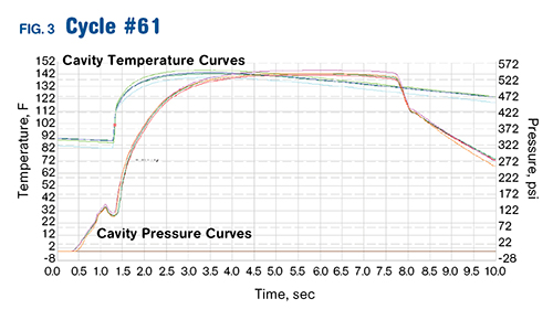
Fig. 3: As cavity temperature becomes more consistent from cavity to cavity in a multicavity mold, so does cavity pressure (see Fig. 2).
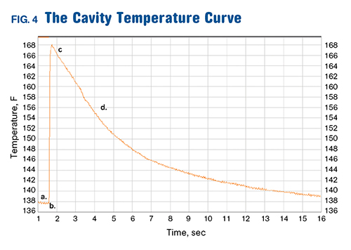
Fig. 4: Typical cavity-temperature curve for a sensor placed near the end of fill. It shows filling (b to c) and cooling (d).
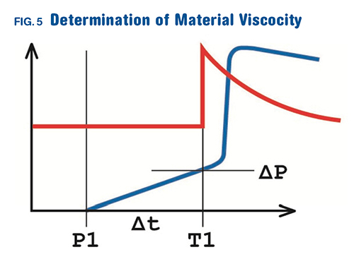
Fig. 5: Cavity-temperature and pressure sensors can be used together to monitor and control melt viscosity. Shear rate is calculated from Δt and shear stress from the pressure at T1.


In plastic injection molding, the primary objective is to manufacture dimensionally and structurally consistent parts, independent of the molding machine being used. To accomplish this, molders can benefit from process optimization and control methods based upon PVT (Pressure-Volume-Temperature) relationships and automatic detection of the melt front*. These methods provide real-time information as the plastic is changing from a liquid to a solid. When the PVT behavior is consistent from cavity to cavity, then consistent parts are produced, making “lights out” molding possible.
The PVT information is obtained from appropriately placed in-mold cavity-pressure sensors and cavity-temperature sensors. Although every application needs thoughtful consideration, there are some general guidelines regarding sensor use and placement as well as reasons why using both cavity pressure and
cavity temperature information is important and beneficial.


USES OF CAVITY PRESSURE
Cavity-pressure sensors provide an ideal source of information for process optimization. Direct or flush-mounted piezoelectric cavity-pressure sensors are recommended due to their high rigidity, natural frequency, measuring range, and signal reproducibility and linearity. If space for flush-mount sensor installation is limited, behind-the-pin sensors can be utilized for process monitoring and development. However, over time, plastic and other substances can accumulate in the ejector-pin channels, which can interfere with pin movement. This leads to unreliable pressure signal readings.
In general, Priamus recommends placing a pressure sensor near the gate, within the first third of the flow path. More information is obtained from the cavity-pressure curve when the sensor is near the gate, compared with a sensor that is towards the end of fill. A pressure sensor near the gate will show the entire
filling phase and provide more options for controls. (In some special cases, using a cavity-pressure sensor at the end of the flow path is indicated.) Specialists in in-cavity sensing, like Priamus, can offer suggestions for sensor placement in specific applications.
See Fig. 1 for key points described by the cavity-pressure curve:
a) Material passing the sensor: When the pressure signal rises from zero, the material is crossing the pressure sensor. Automatic detection of the melt front* at this point can be used for process control. In order to detect this, sensors and corresponding electronics must be able to respond within fractions of a millisecond.
b) Injection: The slope of the initial rise from zero can indicate the rate of injection. The injection profile can be optimized so that consistent melt-front velocity is achieved. This affects part shrinkage.
c) Switchover/transfer: The beginning of the rapid increase to maximum pressure indicates when the machine transfers from injection to hold. If there is a dip in the curve at this point, the process could be transferring too early, or is indicative of hold-pressure filling. This induces internal stresses in the part. A
fixed level of cavity pressure can be set and used for transfer.
d) Peak pressure: The peak point on the curve is the maximum pressure inside the cavity. The time to reach this point after transfer depends upon the reaction time of the molding machine.
e) Gate seal: On the descending side of the curve, the slope should decrease smoothly. If the curve has a sudden drop, the gate may not be sealed. Note that when the cavity-pressure curve arrives at atmospheric
pressure, this has a 1:1 correlation with part shrinkage.
USES OF CAVITY TEMPERATURE
Cavity-temperature sensors provide an instantaneous indication of melt-front location, more quickly than would be possible with cavity-pressure sensors. When placed directly or flush mounted in the last 10-15% of the flow path, material viscosity changes and cavity fill-time deviations are ascertained immediately. For example, in a hot-runner multi-cavity tool, temperature sensors placed towards the end of fill in the same location of each cavity can be used for automatic balancing* so that all cavities fill equally at the same time.
As the cavity-temperature traces become consistent, the cavity-pressure curves also become consistent (see Figs 2 and 3). This is inherent in the PVT behavior of the plastic. For larger molds with multiple gates, temperature sensors placed near each of the gates can be used to control the opening or closing of the
individual gates.*
See Fig. 4 for key points described by the cavity temperature curve:
a) Mold steel temperature: Before the material reaches the sensor, the mold-steel temperature deviations from cavity to cavity can be seen. Blocked cooling lines can be quickly identified over time as the mold surface temperatures may show an increase. In addition, a mold insert is easily detected as there is a temperature drop before the material is detected in the cavity.
b) Material location in the cavity: When the temperature curve spikes rapidly, the material has reached the sensor. This signal can be used for automatic switchover or transfer to holding pressure.* It is possible to optimize this point using a slight signal-delay function.
c) Maximum temperature: This is a “contact” temperature, not a melt temperature. The maximum point of the temperature curve will be much lower than the temperature at which the material is initially injected.
d) Cooling of the cavity: The decline of the curve indicates the mold-cooling effectiveness in the specific location of the sensor. If the curve reaches the initial mold-steel temperature by the time the mold opens, the cooling is good in this location. This information can be used to optimize cooling time and reduce cycle time.
USING BOTH CAVITY TEMPERAT URE & PRESSURE
When a cavity-pressure sensor near the gate is used together with a cavity-temperature sensor near the end of fill, material viscosity, including shear stress and shear rate, part compression, and shrinkage all can be monitored and controlled. The shear rate is calculated from the time, Δt (see Fig. 5), that the melt takes to flow the distance between the pressure sensor and the temperature sensor. The pressure measured at time T1 is used to determine shear stress. Batch-to-batch material-viscosity variations can be easily identified.
This method of measuring material viscosity provides a quick, easy way to transfer molds to different machines or locations. Process conditions (shear stress and shear rate)—not just machine settings—can be duplicated. Costly tool validations can be eliminated. Shear-stress and shear-rate values obtained from mold-filling simulations can also be matched for faster startups of new molds.
*Priamus U.S. Patent 7,682,535 B2.


Related Content

Are Your Sprue or Parts Sticking? Here Are Some Solutions
When a sprue or part sticks, the result of trying to unstick it is often more scratches or undercuts, making the problem worse and the fix more costly. Here’s how to set up a proper procedure for this sticky wicket.
Read More
Know Your Options in Injection Machine Nozzles
Improvements in nozzle design in recent years overcome some of the limitations of previous filter, mixing, and shut-off nozzles.
Read More
How to Select the Right Tool Steel for Mold Cavities
With cavity steel or alloy selection there are many variables that can dictate the best option.
Read MoreRead Next

Understanding Melting in Single-Screw Extruders
You can better visualize the melting process by “flipping” the observation point so that the barrel appears to be turning clockwise around a stationary screw.
Read More
People 4.0 – How to Get Buy-In from Your Staff for Industry 4.0 Systems
Implementing a production monitoring system as the foundation of a ‘smart factory’ is about integrating people with new technology as much as it is about integrating machines and computers. Here are tips from a company that has gone through the process.
Read More
Why (and What) You Need to Dry
Other than polyolefins, almost every other polymer exhibits some level of polarity and therefore can absorb a certain amount of moisture from the atmosphere. Here’s a look at some of these materials, and what needs to be done to dry them.
Read More