
Avoid Scale Buildup: The Silent Enemy of Cooling Performance
Obstructions in cooling can wreak havoc on molding. Here, a well-known supplier to molders that also molds recounts its experience and offers tips on how you can keep things flowing.
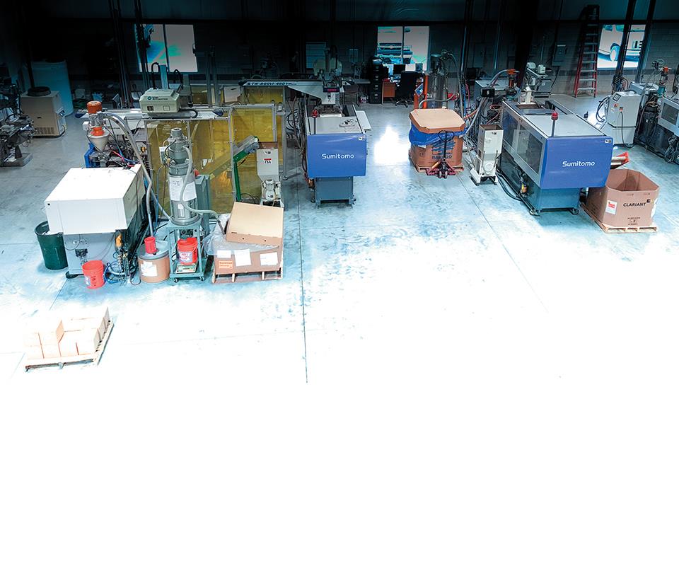
While known primarily as a supplier to molders, Burger and Brown also has a molding department with three all-electric presses from Sumitomo Demag.
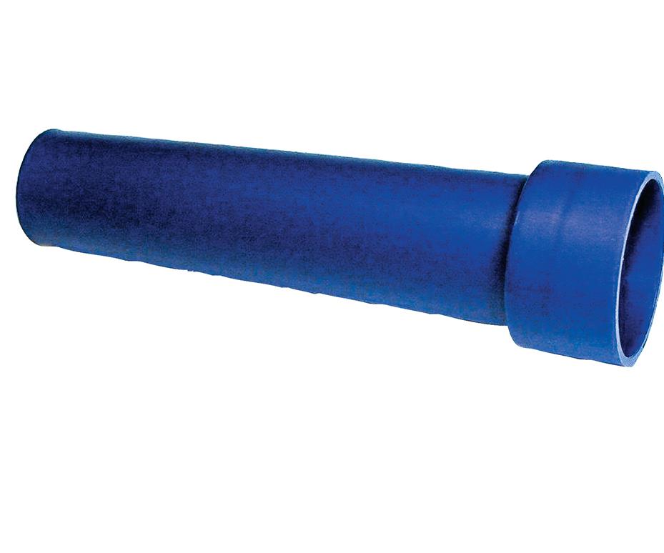
When molding this dispensing spout, Burger and Brown encountered problems later attributed to calcium buildup in the cooling baffles.
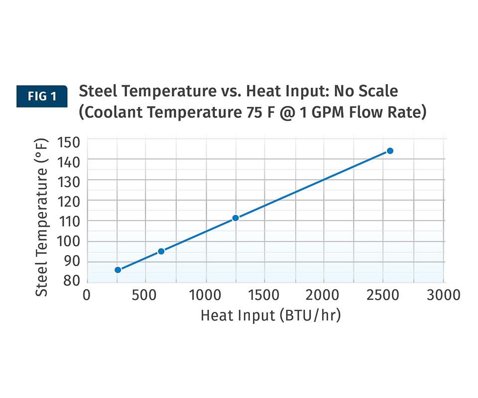
This trial was conducted with a clean cooling channel to establish a baseline of cooling performance. Note that even with a very large heat input of 2500 BTU/hr, the core temperature rises only to about 144 F.
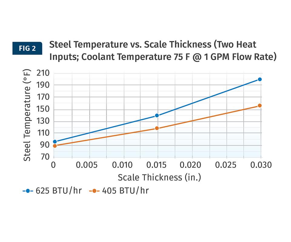
In this test, an acrylic sleeve was pressed into the ID of the cooling channel to simulate scale buildup in the cooling channel. Trials used two acrylic sleeves 0.030-in. and 0.015-in. thick. For a given heat input (cycle time) the core temperatures increase as the thickness of scale increases. This leads to excessive core temperatures and difficulty running good parts.


Burger & Brown Engineering, Inc.. is known in the plastics industry for molding accessory products, Scientific Cooling classes, and for cooling-related technical pieces we’ve written over the years for Plastics Technology (see top right for links).
But Burger and Brown is also a molder with a very modern, highly automated molding department that molds parts for our Smartflow product line and for other manufacturers. Our molding department started with a single new electric press intended to serve as a lab tool for development of our accessory products. It wasn’t long until we were molding production parts for ourselves and others.


In 2003 we were engaged by a local customer to develop a dispensing spout for a liquid product. We assisted in designing the spout and sourcing a 4-cavity, sub-gated, sleeve ejection mold. It was a good opportunity for our small molding operation. The spout is 4-in. long with a 1-in. diam. at the large end. It has a wall thickness of 0.033 in. at the small end and 0.048 in. at the large end. Cooling consists of annular water channels in round cavity inserts and 13-in.-long baffles in the cores. Coolant is delivered to cores and cavities through drilled holes in mold plates, each circuit serving a pair of cores or cavities.
The launch of this new product went well and we enjoyed the new business. After about 4 years we began having difficulty molding the parts. We noticed that the core cooling circuits only allowed a trickle of flow and the cores ran extremely hot. During ejection, parts tended to roll up on the hot cores—even with a painfully long cooling time. We sent the mold to our in-house shop for troubleshooting.
The trouble was not hard to find. The baffle circuits were severely obstructed—so much so that it was impossible to remove the baffles from the cores. We drilled out the long baffles, cleaned up the cooling passages, and installed new baffles. We had learned a useful lesson about maintenance of the mold and the cooling water system. Since then we have improved coolant and tool maintenance and have run the parts on a good cycle since 2007.
Recalling this experience from years ago got us thinking about designing some experiments to quantify the effects of calcium scale in cooling channels. We built a simulated round core—a P-20 steel cylinder, 1.5 in. diam. × 6 in. long with a 7/16 in. diam. blind cooling channel that can be configured to run with a baffle or a bubbler tube. Trials were conducted with a standard bubbler tube. We used precision RTD temperature sensors halfway between the OD of the core and the wall of the cooling passage to measure steel temperature. We provided a heat input to the “molding surface” using three heater bands and a controllable Voltage to simulate the injection of plastic at various rates. Increasing heat input corresponds to speeding up the cycle.
In our lab we have the means to provide coolant flow at different temperatures and precise flow rates. We use an automated multi-channel data-acquisition system to record coolant flow, coolant temperature in and out, and steel temperatures at two sensor-insertion depths. The data is automatically converted to an Excel spreadsheet to allow study and manipulation of the data—creating charts and the like.
Our first series of trials were with a clean cooling channel to establish a baseline of cooling performance. Figure 1 shows steel temperature vs. heat input at a constant coolant temperature of 75 F and 1 GPM flow rate, well above the turbulent transition. Remember, higher heat input is the same as speeding up the cycle—more plastic input/hr equals more BTUs/hr. Note that even with a very large heat input of 2500 BTU/hr, the core temperature rises only to about 144 F.
To simulate scale buildup in the cooling channel, we pressed an acrylic sleeve into the ID of the cooling channel. The acrylic polymer has a heat-transfer coefficient similar to calcium scale. We conducted trials with two thicknesses of acrylic sleeves: 0.030-in. and 0.015 in. Figure 2 shows steel temperature vs. scale thickness in inches. We used two heat inputs that are within the range of the spout mold conditions. Cooling conditions are the same as in Fig. 1.
For comparison, we calculated the actual cooling achieved on the B-Side of the spout mold during production, using coolant flow rate and the change in coolant temperature flowing through the cores. The resulting value was 1892 BTU/hr for 4 cores or 473 BTU/hr per core. Referring to Fig. 1, we can see that with clean cooling channels the core temperatures should be about 90 F.
Figure 2 shows that for a given heat input (cycle time) the core temperatures will increase as the thickness of scale increases. These conditions will lead to excessive core temperatures and difficulty running good parts. At this point the options are to reduce heat input (slow the cycle) or restore the cooling channels to a clean condition.
In our Scientific Cooling class we teach about the effects of scale buildup and students practice the calculations that show the dramatic difference in heat-transfer rate between mold construction metals and calcium scale. But the degree of cooling deterioration illustrated by these experiments was surprising.
The lessons learned are clear. Establish baseline performance data for coolant flow and ΔT (change in temperature) through circuits when the mold is clean. Significant increases in ΔT values or declining flow rate for a given system pressure signals a cooling problem—scale or perhaps an obstruction. Give your cooling-water system the attention it deserves so the chemistry is not working against you. Create and use setup sheets and note changes that occur from run to run. Perform periodic mechanical or chemical de-scaling of cooling circuits. Pay attention to these things and “keep your cool.”
ABOUT THE AUTHOR


Related Content

Machine-Side and Central Chiller Lines, Industry 4.0 Controls to Launch
Frigel will use K 2022 to showcase a number of developments in process cooling, including new and expanded lines of central and machine-side chillers, as well as advanced control platforms.
Read More
Cooling Geometry and the Reynolds Calculation
The original Turbulent Flow Rate Calculator worked well with a round circuit diameter, such as a drilled passage, but not as well using hydraulic diameters. Here’s how the problem was fixed.
Read More
Wisconsin Firms Unite in Battle Against Covid
Teel Plastics opened new plant in record time, partnering with AEC & Aqua Poly Equipment Co. to expand production of swab sticks to fight pandemic.
Read More
Cooling the Feed Throat and Screw: How Much Water Do You Need?
It’s one of the biggest quandaries in extrusion, as there is little or nothing published to give operators some guidance. So let’s try to shed some light on this trial-and-error process.
Read MoreRead Next

TOOLING: Balancing the Heat Budget In Injection Molds
Basic formulas for how much heat you must pull out of the mold to achieve a set cycle time
Read More
Leverage Your Cooling Power
You can predict the amount of heat you'll need to remove from parts before ejection with reasonable accuracy if you know polymer thermal properties and certain other rules of thumb.
Read More
Improve The Cooling Performance Of Your Molds
Need to figure out your mold-cooling energy requirements for the various polymers you run? What about sizing cooling circuits so they provide adequate cooling capacity? Learn the tricks of the trade here.
Read More