In North America, extruders are typically made with a cast feed section having cooling passages that are molded directly into the casting near the feed throat.
On this extruder, a longer barrel is used, and the feed port is machined directly into the barrel cylinder and liner.
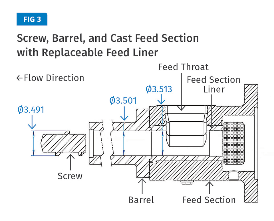
An optional removable and replaceable feed-section liner in a cast feed section protects against accidental damage or long-term wear and can be swapped out when you want to change feed-throat geometries or replace a damaged feed throat.
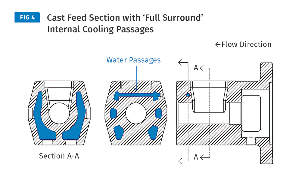
Here, the cast feed section is cored for water cooling that fully surrounds the feedscrew to prevent premature melting of the polymer flowing from the hopper.
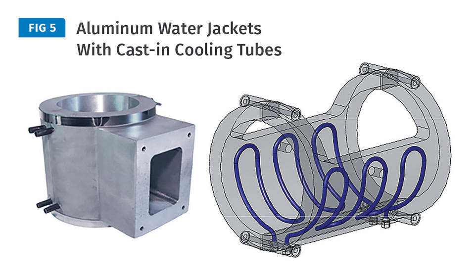
With an integral barrel/feed throat, an aluminum water jacket with cast-in cooling tubes would typically be used to cool the outside surface of the barrel.


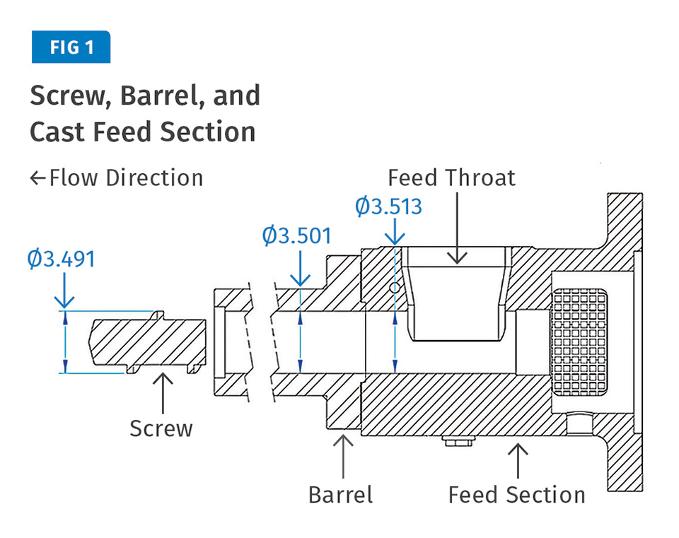
Feed-section design plays an important role in the extrusion process and should be carefully considered when specifying a new extruder. Most single-screw extruders operating in North America include a cast feed section with cooling passages that are molded directly into the casting near the feed throat. As shown in Fig. 1, the feed casting is bolted to the upstream side of the barrel. It acts as a thermal barrier, which prevents polymer bridging (early melting) on the feed-throat walls and melt blocks in the feed section of the screw. It also minimizes heat transfer from the barrel to the gear reducer.
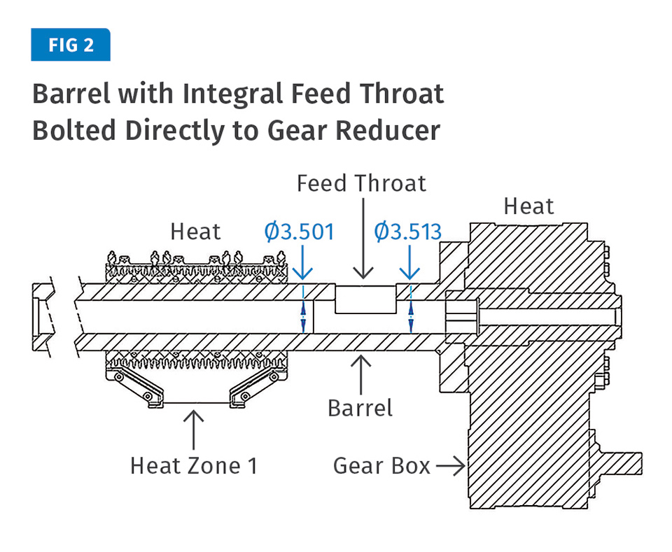
An alternate design offered by some extruder manufacturers is a single-piece barrel with an integral feed port. This design uses a longer barrel, and the feed port is machined directly into the barrel cylinder and liner (see Fig. 2).


Studies have indicated the potential for increased output rate when processing certain polyolefins with this single-piece approach. In a paper delivered at the Society of Plastics Engineers’ ANTEC 2007, well-known extrusion consultant Tim Womer and others studied the differences in output rate of 100% PP regrind (2 MI) and 100% HDPE regrind (0.3 MI) on a 3.5-in., 24:1 L/D extruder with either a barrel with integral feed port or a water-cooled, cast-iron feed section. Each test included five different screw speeds, and the integral-feed-throat configuration produced more output at every screw speed than the standard barrel with water-cooled cast feed section. For example, there was an increase in output rate of 5.25% for PP and 3.93% for HDPE when running at 75 rpm screw speed.
Due to the increased output rate, the motor amp draw and melt temperature also increased with the integral configuration compared with the water-cooled cast feed section. The increase in solids conveying and output rate is attributed to the heat migration from using an integral barrel/feed-port configuration that increases the coefficient of friction between the pellet and the barrel wall in the feed section of the screw. The extra heat input to feed zone moves the onset of initial melting back toward the hopper, which is beneficial for certain polymers.
Studies have shown the potential for an increase in output rate when processing certain polyolefins on extruders designed with a single-piece barrel and an integral feed port.
Although increased output rates for PP and HDPE may be attractive, there are several risks and downsides when considering the purchase of an extruder with an integral barrel/feed throat, especially when a processor has multiple extruders with the more common water-cooled, cast-iron feed section.
Here are the key considerations:
1. An optional removable and replaceable feed-section liner on a separate cast feed section (Fig. 3) protects against accidental damage or long-term wear. With the integral barrel/feed-throat design, you have to swap out the entire barrel when you want to change feed-throat geometries or replace a damaged feed throat.
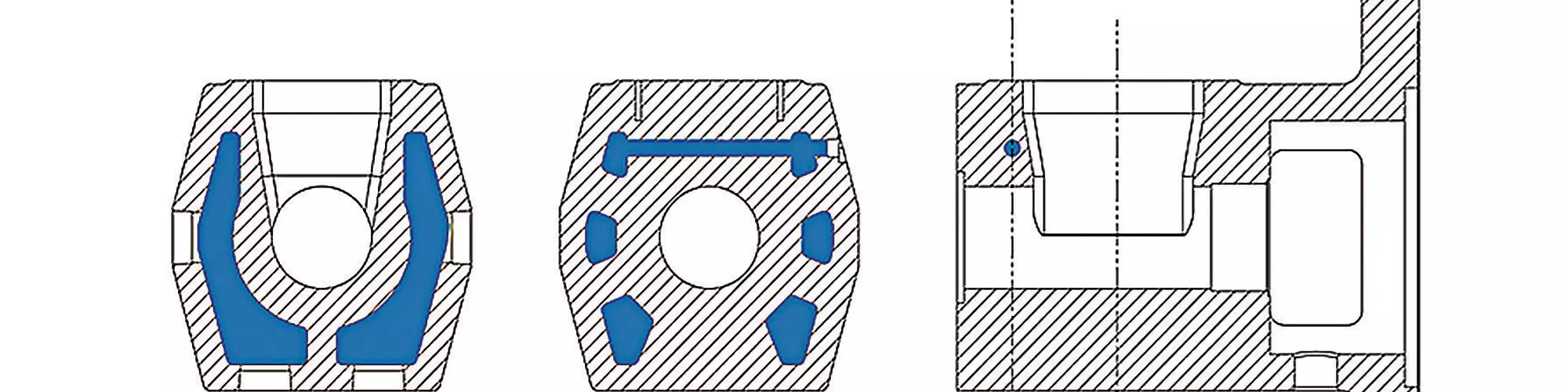
2. A cast feed section, cored for full-surround water cooling (Fig. 4) surrounds the feedscrew to prevent premature melting of the polymer flowing from the hopper. The outside temperature of the casting is typically 90-120 F, or “warm to the touch.” The issue with an integral barrel/feed throat is that the barrel acts as a big heat pipe, and heat flows into the feed throat zone. It is harder to effectively control the feed-throat temperature without it being affected by the first barrel zone. The separate cast feed section provides a thermal barrier that results in greatly reduced thermal conduction from the first barrel zone.
With an integral barrel, the area of conduction is much larger, necessitating much more cooling for the feed throat. From a screw-design and extruder-performance standpoint, it would be better to have a separate feed section with a good thermal barrier to control the amount of heat transfer into the feed throat. Excessive heat in the feed throat can cause bridging problems where the pellets traveling down the throat will start to melt prematurely and clump up.
Low-melting-point polymers are most susceptible to sticking to the wall of the feed throat. As the pellets build up on the feed-throat walls, material flow is restricted or blocked as it enters the extruder, and gradually there is a decrease in output rate. Cooling of the feed throat is very important to prevent bridging. Removing the partially melted clump of material blocking a feed throat can be difficult and dangerous, and can result in significant downtime.
3. It is harder to machine efficient cooling channels in the feed housing. Typically, an aluminum water jacket with cast-in cooling tubes would be used with the integral barrel/feed throat (Fig. 5), which cools the outer surface of the barrel, unlike more efficient internal cooling passages within a cast feed section. Air cooling the feed section with a blower is much less efficient and mostly inadequate, especially as the extruder size increases. The larger the extruder size, the greater the mass of the barrel and the thicker the barrel wall, which increase the heat-removal requirement. Air only has a gentle effect on the barrel; water cooling is better for fast heat removal, and thus water cooling is the most effective method to cool the feed throat. Air cooling would also depend on the ambient temperature, which is apt to differ between summer and winter.
4. Higher feed-zone temperatures increase potential for melt-block problems in the feed section. A melt block is when output rate and motor amps fall due to a loss of solids conveying due to polymer sticking to the screw root in the feed zone. This usually happens when the extruder is stopped—even for a few minutes—with the screw full of polymer. The screw surface under the hopper becomes hot during a screw stoppage. Polymer stuck on the screw root will rotate with the screw, reducing the screw channel area, resulting in flow surging and a loss of output rate. Even small traces of polymer stuck to the screw root can cause flow surging issues.
The fix to a melt-block problem often requires pulling the screw for a full cleanout. With small extruders, the screw can be pulled and cleaned in a few hours. However, pulling and cleaning a large screw by hand may take half a day or longer. Because the integral barrel/feed-throat design does not include a thermal barrier (cooling break) you must have constant water flow to the feed-throat area, especially during a stoppage.
5. As mentioned previously, the cast feed section minimizes heat transfer from the “hot” barrel to the extruder gear reducer (Fig. 2). The barrel/screw and gear reducer both generate heat, and the cast feed section acts as a heat sink and absorbs heat between the two devices.
The normal operating temperature of common extruder gear reducers is 130-160 F and depends on the gearbox’s heat dissipation. Without the thermal barrier of a cast feed section between the barrel and the gear reducer, as in the integral barrel/feed-throat design, heat will migrate to the extruder gear reducer. Excessive heat around the output shaft area of the gear reducer may result in premature failure of the output-shaft radial seal ring. In addition, use of an integral barrel/feed throat bolted directly to the gear reducer may necessitate the need for a cooling coil to be added to the gear reducer, when it would otherwise not be needed with a cast feed section bolted to the gear reducer.
6. If a processor has several extruders with traditional watercooled, cast-iron feed sections running certain polymers, and then decides to change to an extruder with an integral barrel/feed throat to run the same polymers, then the processor would likely have to modify its barrel-temperature profiles to compensate for the higher melt temperatures associated with the integral barrel/feed throat.
7. The extra heat input into feed zone with the integral barrel/feed throat moves the onset of initial melting back toward the hopper. Similarly, preheating the feedstock results in faster melting because a substantial amount of heat is conducted into the polymer in the hopper. Using an integral barrel/feed throat in conjunction with the preheated feedstock has shown to cause air-entrapment issues while running preheated amorphous PET pellets mixed with a high percentage of preheated, recycled A-PET thin flake.
Flake feedstocks can contain up to 70% air by volume, and air is also between the pellets. The air is squeezed out and flows backward into the hopper from the feed throat as the pellets are compacted into a solid bed along the screw prior to melting. The issue is that thin regrind flake will melt too quickly in the feed zone before compaction is complete, blocking the air from flowing backward to the hopper and trapping air in the melt, resulting in defects in the final product. The early melting phenomenon seen in preheating flake with an integral barrel/feed-throat design would likely not occur with a separate water-cooled cast feed throat.
INTERCHANGEABLE SCREWS?
Processors typically ask if screws are interchangeable between extruders with a cast feed section and ones with an integral barrel/feed throat. The answer is no. Even if the main flight OD, screw shank, and the overall length of the screws are the same, the concept of screw “interchangeability” between the two extruder designs cannot be fulfilled in the context of mechanical design and screw processing performance.
The clearance between the screw and the barrel and feed section is a very important factor in extruder design. Most extruders are designed with a feed screw with full diameter throughout the flighted length and a cast-iron feed section that has a slightly larger bore ID compared with the barrel bore ID, as shown in Fig.1. When the screw and barrel increase in temperature, both the screw and barrel will increase in diameter due to thermal expansion. The clearance between the screw and the barrel and feed section will reduce with increasing temperature.
In a running extruder, the screw, barrel and feed section are not at the same temperatures. A large amount of viscous heat is generated as the melt is sheared by screw rotation. When viscous heating is significant, the screw temperature will likely to be higher than the barrel temperature, and the largest difference in temperature will be between the screw and the feed throat.
“Of the thousands of extruders equipped with a cast-iron feed section, I have not seen any issues with the screw becoming stuck in an extruder barrel due to misalignment.”
The feed throat is typically water cooled in the 90-120 F range, and the screw temperature in the feed section will be much higher because the high temperatures in the compression and metering section will raise the temperature of the screw in the feed section due to thermal conduction. If the feed-bore ID and the barrel ID are the same as in an integral barrel/feed throat design, then as the screw heats up it will expand against the “cold” feed-section bore that doesn’t expand and binding and galling will likely occur.
That is why the cast iron feed section has a slightly larger bore ID compared with the barrel-bore ID; or alternatively, the screw flights in the feed section are undercut. The higher screw temperature will cause the screw to expand much more than the feed throat and the barrel, and therefore there is less chance for catastrophic failures from the screw locking up in the feed section.
The only way to solve this with the integral barrel/feed-throat design is to grind a relief into the inlay of the barrel in the feed area (Fig. 2) or undercut the screw to increase the flight clearance. Grinding a relief in the barrel inlay is not a common practice in the industry, and it is likely that in the future the relief will be mistaken for feed wear. Undercutting the screw in the feed will have an adverse effect on screw performance if the screw is later used in an extruder with a common oversized feed-bore ID, because the clearance between the screw-flight OD and the feed-bore ID will be large enough to allow small feedstock particles such as powder, additives and “fines” to pass over the top of the flights, reducing the ability to convey solids out of the feed section. Even worse, if the standard screw that does not include an undercut in the feed area were to be used in the extruder with an integral barrel/feed throat without a relief in the feed, the screw would almost certainly bind and catastrophically lock up in the feed section.
WHICH DESIGN OFFERS BETTER ALIGNMENT?
Extruder manufacturers that offer the integral barrel/feed throat claim that this design offers improved alignment between the barrel and gearbox. Barrel and feed-section misalignment can cause problems; however, of the thousands of extruders operating around the world equipped with a cast-iron feed section, I have not seen any issues with the screw becoming stuck in an extruder barrel due to misalignment. It is important to remember that the screw is supported and centered in the barrel hydraulically by the internal pressure of the polymer in the screw channels.
Efficient and uniform water cooling of the feed throat is important for many polymers to ensure feeding consistency and to reduce the chances of feed bridging. The integral barrel/feed-throat design is rife with unknowns and potential risks, especially in larger extruders, where it is more difficult to control the temperature of the integral barrel/feed-throat section.
The integral barrel/feed-throat design is a low-cost approach to extruder design that may result in high output rates but not necessarily improve the quality of extrusion. Extensive lab experiments would need to be completed to demonstrate the effectiveness through a range of extruder sizes and with a wide variety of polymers and feedstocks, including powders and recycled material.
ABOUT THE AUTHOR: Steve Maxson is v.p. of marketing and sales for Fermatex Vascular Technologies, a leading designer and manufacturer of high-pressure braided tubing, complex medical extrusions, and advanced catheters. He was previously director of business development for extrusion at Graham Engineering Corp., York, Pa., and has held sales management positions with the medical-device companies Raumedic and Vante. He is based in Hickory, N.C. Contact: 828-308-2588; smaxson@fermatex.com; fermatex.com.
Related Content

Understanding Melting in Single-Screw Extruders
You can better visualize the melting process by “flipping” the observation point so that the barrel appears to be turning clockwise around a stationary screw.
Read More
Understanding the ‘Science’ of Color
And as with all sciences, there are fundamentals that must be considered to do color right. Here’s a helpful start.
Read More
Avoid Four Common Traps In Granulation
Today, more than ever, granulation is an important step in the total production process. Our expert explains a few of the many common traps to avoid when thinking about granulators
Read More
How Polymer Melts in Single-Screw Extruders
Understanding how polymer melts in a single-screw extruder could help you optimize your screw design to eliminate defect-causing solid polymer fragments.
Read MoreRead Next

Processing/Workplace Safety Tips for Fluoropolymer Medical Tubing
Here's what you need to know and running these emerging materials for medical tubing.
Read More
How Polymer Melts in Single-Screw Extruders
Understanding how polymer melts in a single-screw extruder could help you optimize your screw design to eliminate defect-causing solid polymer fragments.
Read More
Troubleshooting Screw and Barrel Wear in Extrusion
Extruder screws and barrels will wear over time. If you are seeing a reduction in specific rate and higher discharge temperatures, wear is the likely culprit.
Read More