
Cooling Geometry and the Reynolds Calculation
The original Turbulent Flow Rate Calculator worked well with a round circuit diameter, such as a drilled passage, but not as well using hydraulic diameters. Here’s how the problem was fixed.


It has been more than nine years since we presented our first Scientific Cooling class. Over these years we made nine revisions to improve the content. We created a metric, Scientific Cooling, and more recently, during Covid-19 times, we developed a narrated virtual Scientific Cooling course.
As the name suggests, the content is about cooling and heat transfer, the process of moving heat from one place to another. The two most important lessons might be: How do we quantify how much heat must be removed from a shot of a particular molten polymer; and how do we determine the cooling process required to sufficiently cool that shot?


A Reynolds Calculator Design
Nearly two-thirds of the Scientific Cooling training involves learning and practicing calculation skills related to polymers, heat transfer, coolant properties, and Reynolds number. There is great value in learning to perform these calculations manually and to fully understand the principles and meaning of the calculations. That said, we thought it would be very convenient to have a simple web-based calculator that could do most of the work and quickly generate the desired information. The Reynolds number calculation lent itself very well to creating such a tool.
We imagined a calculator that would determine Reynolds number based on four simple values: cooling-circuit diameter, coolant velocity, coolant kinematic viscosity (presumed to be water), and coolant temperature. Kinematic viscosity is influenced by water temperature. The units in the calculation are unfamiliar and devilish to the average person. Our calculator would perform all the unit conversions behind the curtain, so to speak. Then, with the capability of an Excel spreadsheet, the user experience would be intuitive and user friendly.
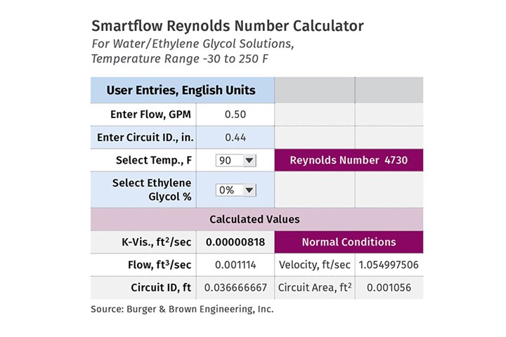
We began by building a prototype calculator using a simple dashboard with an area for inputs including flow rate, coolant temperature, cooling-circuit diameter and ethylene glycol percent. The calculated results included Reynolds number, kinematic viscosity, flow rate in ft3/sec, coolant velocity in ft/sec, circuit internal diameter in ft, and circuit area in ft2.
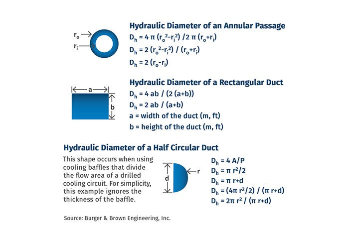
The calculator worked well in experiments with a round circuit diameter, such as a drilled passage. It was my belief that we could also calculate accurate Reynolds numbers by simply entering a hydraulic diameter value. Our simple one-page chart (see table below) shows a number of these shapes and how to calculate the hydraulic diameter.
I experimented with hydraulic diameter values in the calculator and soon realized that something was wrong. The Reynolds numbers calculated using hydraulic diameters were wildly incorrect. I didn’t understand the problem and decided to contact my colleague and friend, Dave Crispino. Dave is a mechanical engineer with an extensive background in injection molding.
When I spoke with Dave about my calculator problems, I learned that he had developed calculating tools that he used in his everyday work. While my calculator was similar, Dave’s approach dealt with the hydraulic diameter issue in a clever and elegant way (see table below). The rest of this article is based on Dave’s thoughts and methods for solving the hydraulic diameter problem as it applies to irregular cooling-passage shapes.
Knowing the Reynolds number of a liquid coolant flowing through a cooling circuit is vital to ensure optimum heat transfer within the mold. A high Reynolds number (usually above 4000) indicates the flow is turbulent. Turbulent flow results in a convective heat-transfer coefficient (between the cooling-channel wall and the coolant) that is an order of magnitude greater than that of a laminar flow. Simply put, for the same temperature difference, a turbulent flow can transfer heat at a rate at least 10 times greater than a laminar flow.
Most cooling circuits in a mold are circular cross-sectional channels. However, sometimes they are not. Cooling components, such as bubblers, baffles, and non-round channels are often necessary. Determining the Reynolds number for flows within these special geometries requires cautious attention.
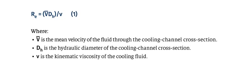
Calculation of the Reynolds number (Re) begins with the following expression:
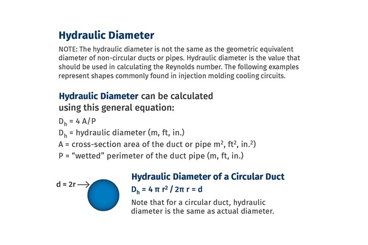
The hydraulic diameter for a cross-section is given by the following:

For a cooling channel with a circular cross-section, the hydraulic diameter is simply the diameter of the cross-section:

When calculating the Reynolds number, it is more convenient and useful to use the volumetric flow rate rather than the mean velocity. The volumetric flow rate can be expressed as gallons per minute, cubic inches per second, liters per minute or whatever units you choose to work in. We represent the volumetric flow rate with the variable Q. The mean velocity is related to the volumetric flow rate with the following expression:

It is important to remember when calculating the mean velocity that the area A in equation (4) is the actual area of the cross-section and not the area of a circle defined by the hydraulic diameter. This is a common mistake made when calculating the Reynolds number for a non-circular cross-section and leads to inaccurate results.
One way to avoid this mistake entirely is to remove any area computation from the calculation. If you substitute equations (2) and (4) into equation (1) you get the following:

The area A appears in both the numerator and the denominator and therefore cancels out. The expression for the Reynolds number reduces to:

Equation (6) is a useful expression to determine the Reynolds number for any cross-sectional geometry in terms of volumetric flow rate and wetted perimeter. Using this method, there is no need to determine the hydraulic diameter or calculate the cross-sectional area. This eliminates the possibility of making the above-mentioned mistake entirely.
The development of the Turbulent Flow Rate Calculator was thus completed, providing a very broad coolant-temperature range and many safety and convenience features that assist in the selection of appropriate coolant temperatures, flow rates, and water/glycol solutions. David Crispino’s method for Reynolds number calculation was a key contribution to completing the Burger & Brown Engineering Turbulent Flow Rate Calculator.
ABOUT THE AUTHOR: Phil Burger, P.E., founded Burger & Brown Engineering Inc. in 1978 and served as president until 2005. Burger & Brown manufactures engineered products related to mold cooling and in-mold sensing and holds 10 patents for its products. Burger currently works part-time for the firm and has most recently developed an educational program called Scientific Cooling that was launched in October 2013. The class covers energy principles and the relationship to specific polymers, turbulent flow, Reynolds Number, detailed heat transfer calculations, and how to design a cooling circuit that produces predictable cooling results. Contact: (816) 878-6675; pburger44@gmail.com; smartflow-usa.com.
David Crispino Ph.D, has worked in plastics for 38 years. He is currently employed as a senior engineer for EG Industries, Rochester, N.Y., a custom molder and moldmaker. Contact: (585)-627-2300 x 6210; djcrispino@egindustries.com; egindustries.com.


Related Content

How to Get Rid of Bubbles in Injection Molding
First find out if they are the result of trapped gas or a vacuum void. Then follow these steps to get rid of them.
Read More
How to Select the Right Tool Steel for Mold Cavities
With cavity steel or alloy selection there are many variables that can dictate the best option.
Read More
How to Stop Flash
Flashing of a part can occur for several reasons—from variations in the process or material to tooling trouble.
Read More
The Effects of Temperature
The polymers we work with follow the same principles as the body: the hotter the environment becomes, the less performance we can expect.
Read MoreRead Next

Avoid Scale Buildup: The Silent Enemy of Cooling Performance
Obstructions in cooling can wreak havoc on molding. Here, a well-known supplier to molders that also molds recounts its experience and offers tips on how you can keep things flowing.
Read More
An Engineering Approach to Mold-Cooling Circuit Design
The Energy Density vs. ΔT/in. relationship is an important step forward in pursuit of a science-based approach to cooling-circuit design. Here’s why.
Read More
An Inside Look at Turbulent Flow
Years of talk about observing and studying coolant flow in a clear simulated cooling channel finally becomes a reality. Here’s how it all came together, and what it all means.
Read More