
Cures for Common Hot-Runner Wiring Problems
In the challenging environment of the last several years, manufacturers are looking inward to improve their manufacturing processes, streamline their supply chains, lower maintenance costs, andimprove their bottom lines.
Pin push-out decreases or eliminates contact with the mating pin. The simplest solution is to use high-quality components from a respected manufacturer, and avoid mixing brands unless you have verified that there are no tolerance issues.
Pin burn-out and short circuits are often caused by using a typical 10-amp connector for a 15A circuit.
Cable pull-out is usually caused by excessive manual loading and improper strain relief.
Cable failure is costly. The most effective way to avoid it is proper wire sizing and using flex-rated cables and conduit, where appropriate.


In the challenging environment of the last several years, manufacturers are looking inward to improve their manufacturing processes, streamline their supply chains, lower maintenance costs, and improve their bottom lines. Injection molders are frustrated with the costs associated with failing power and thermocouple cable assemblies in hot-runner systems. These costs include tool or controller damage, cable repair or replacement, loss of production, strained customer relations, overtime expenses, and much more.
Power and thermocouple assemblies come in a variety of configurations, many of which are based on rectangular connectors similar to those made by Harting, Inc., Elgin, Ill. (hartingusa.com). Unfortunately, in many cases components from different suppliers are mixed and matched in the same assembly and/or application. This contributes to increased failure rates. Key factors are connector manufacturing quality, design tolerances, cable types, cable gauges and strain-relief selection. To minimize this, you need properly sized, UL-listed connector and cable components.


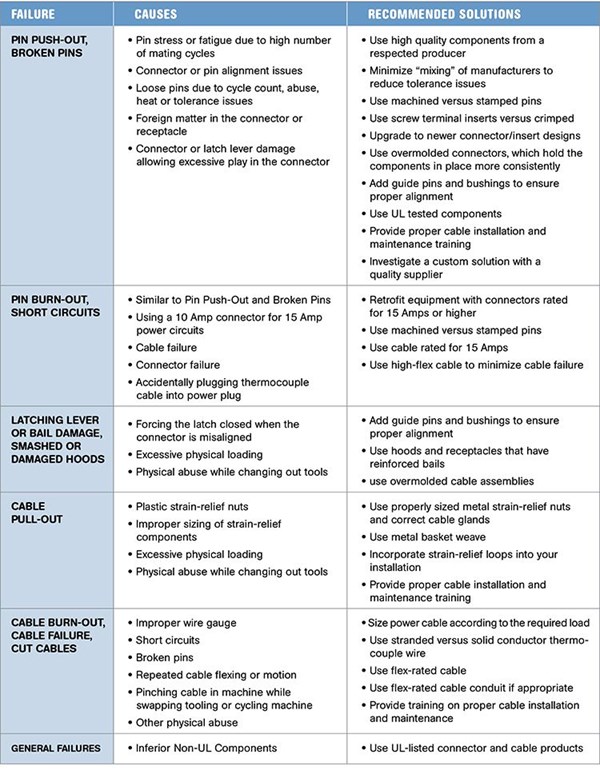
Failures on the production floor are simple to understand. Uncovering their root causes and solutions takes a bit more research and insight into cable assembly construction and use over their life cycles. Common failure modes and remedies are summarized below. In reviewing them, keep in mind the following key principles:
•Proper cable installation and application will reduce downtime, repair and replacement costs.
•Reliability is often lacking in cable assemblies produced under current industry practices.
•Current industry design standards need to be re-evaluated.
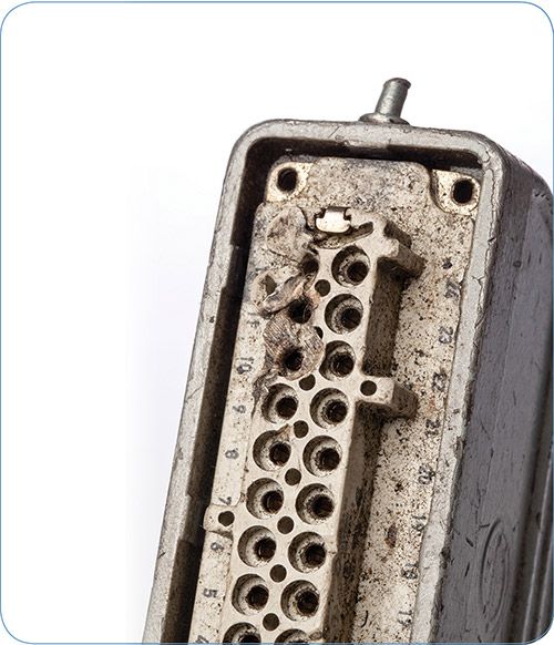
PIN PUSH-OUT/PIN BREAKAGE
Pin push-out decreases or eliminates contact with the mating pin. Some causes are:
•High number of mating cycles.
•Improper alignment and/or forcing the connectors together.
•Tolerance mismatches between connector manufacturers.
•Loose tolerances from the manufacturer.
•Connector damage due to over-current or heat.
The simplest solution to reduce or eliminate pin push-out or breakage is to use high-quality components from a respected manufacturer. Avoid using multiple brands of connectors unless you have verified that there are no tolerance issues.
Machined contacts can reduce the occurrence of pin-push out and are more durable than stamped or formed contacts. Since machined contacts are solid, they provide improved electrical characteristics due to greater contact surface and tend to stay fixed in the connector more reliably. Female machined contacts have more “wall” material than stamped or formed contacts. This improves pin holding forces between male and female contacts. They can also withstand greater amounts of abuse. Additional benefits of machined contacts are:
•Uniform thermal transfer, reducing hot spots and pin burnout.
•Uniform contact surfaces, improving current characteristics.
•Greater resistance to unintentional abuse, minimizing pin breakage.
Connector misalignment can cause pin push-outs and breakage. Guide pins and bushings are very inexpensive, easy to install, and reduce the chances of connector misalignment. Guide pins simply replace the connector-insert mounting screws.
Upgrade your connectors to a newer design. A common older standard for hot-runner power cables is a 25-pin connector with crimped pins. This can be switched out for a newer 32-pin crimp connector that fits a 16B sized hood and housing. This conversion offers three very important benefits:
1. It uses robust machined contacts vs. smaller, stamped/formed D-Sub contacts typically found in the 25 pin connector.
2. It is rated for 16 amps versus the 10A rating of the 25-pin connector.
3. The newer design holds the pins in more reliably.
Lastly, standardize on screw terminal connectors or upgrade to overmolded cable assemblies. These “encapsulate” or “capture” the pins so push-out is not possible. Broken pins can be drastically reduced. The 24-pin screw-terminal connector used on hot-runner thermocouple cable assemblies is an excellent example. By adding “coding pins,” it is possible to standardize on this connector for power and thermocouple cable assemblies.
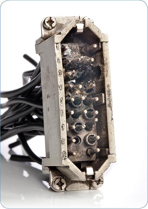
PIN BURN-OUT/SHORT CIRCUITS
Pin burn-out is a catastrophic connector failure caused by current overload or a short circuit. Using a 10-amp connector for a 15A circuit is a major contributing factor. The typical 25-pin crimp connector used in hot-runner power cable assemblies is rated for 10A.
Other causes include cable failures, broken pins, and pin push-out. Reducing costs associated with pin burn-out is simple: Use UL-listed connectors and cables rated for at least 15 amps.
CONNECTOR DAMAGE
Mechanical damage can be a more difficult issue. Connectors get dropped, caught in the tools, run over by forklifts, and subjected to other abuses. Broken latches, damaged latch “bails,” cracked or smashed hoods, and broken mounts are just a few examples of connector damage found on plastic injection presses.
Latches are damaged by excessive physical loading on the latch while it is plugged in, by being latched while there is a misalignment issue, or by random physical abuse. Switching from top-entry (straight) to side-entry (90°) hoods may help reduce mechanical loading on the latch assemblies. This may not be possible in all cases, due to physical constraints of the system. Most standard hoods and housings come in both single-lever and dual-lever designs. Dual-lever designs distribute the physical load better. Guide pins and bushings also can be installed to prevent connector misalignment.
Overmolded rectangular cable assemblies are an additional option. Their key benefits are:
•They eliminate conductor stress and contact push-back to help reduce system failures.
•Their 250-lb pull-out force rating eliminates cable pull-out.
•Omni-directional flex-strain relief reduces cable failures and cable pull-out.
•Overmolding process ensures reliable connections in harsh environments.
•They decrease downtime and maintenance costs related to damaged hoods or latch pins.
•Available in flex or static/tray for total design flexibility.
Lastly, proper employee training can provide the greatest improvement in connector life.
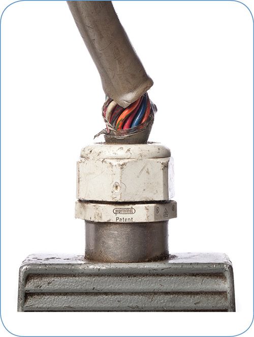
CABLE PULL-OUT
Excessive mechanical loading and improper strain-relief selection are the primary causes of cable pull-out, allowing the cable to work itself out of the backside of the connector. This increases the likelihood of cable failure, pin push-out, and short circuits. Some contributing factors are:
•Low-cost plastic strain-relief compression nuts.
•Improperly sized cable glands.
•Mechanical loading perpendicular to the connector.
•Excessive cable bend radiuses.
•Cable jacket degradation.
Proper strain-relief design is the solution. Select cable glands based on the cable OD and installation environment to ensure a tight fit and to maximize holding force. Do not use plastic compression nuts. These can loosen due to thermal expansion and contraction, vibration, or gland-nut failure. Plastic strain-relief nuts will degrade over time from exposure to heat, ozone, or UV light and should therefore be checked often. Metal strain-relief nuts can be tightened more securely than plastic and will not degrade over time.
Jacket materials on hot-runner cables can be degraded by chemicals, heat, ozone, and UV exposure. Make sure that you select the appropriate jacket material for your manufacturing environment. Two common jacket materials are PVC and TPE.
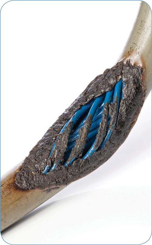
CABLE FAILURE
Cable failure is costly. Common causes are:
•Current overload – running 15A circuits through a 10A cable.
•Physical abuse—pinching, cutting, or smashing the cable in tooling or other equipment.
•Heat—internal or adjacent to the cable.
•Stress from repetitive movement.
•Improper strain relief and tight bend radius.
Proper wire sizing is the most effective way to minimize costs associated with short circuits or burnt-up cables. Do not use a connector rated for 10A for a 15A application. Cables intended for 15A should be 16 Awg or more depending on the cable length.
Flex-rated cable, such as the Alpha XM Series (Flex Control) or Alpha F Series (Continuous Flex) from Alpha Wire & Cable, Elizabeth, N.J. (alphawire.com), reduce failures caused by repeated flexing. Running individual wires through a flex-rated conduit also reduces failures. Flexible power cable solutions are fairly simple. Flexible thermocouple cable solutions are more challenging. Sourcing flex-rated thermocouple wire and cable can be difficult and costly. Typical thermocouple wire uses a solid conductor, which does not accommodate flexing and will fail. Thermocouple cable assemblies should use stranded thermocouple cable or single-pair stranded thermocouple wire in flex-rated conduit. The reduced failure rates will offset the added cost.


Related Content

3D Printing of Injection Molds Flows in a New Direction
Hybrids of additive manufacturing and CNC machining can shorten tooling turnaround times.
Read More
Why Shoulder Bolts Are Too Important to Ignore (Part 2)
Follow these tips and tricks for a better design.
Read More
How to Mount an Injection Mold
Five industry pros with more than 200 years of combined molding experience provide step-by-step best practices on mounting a mold in a horizontal injection molding machine.
Read More
Tunnel Gates for Mold Designers, Part 1
Of all the gate types, tunnel gates are the most misunderstood. Here’s what you need to know to choose the best design for your application.
Read MoreRead Next

Processor Turns to AI to Help Keep Machines Humming
At captive processor McConkey, a new generation of artificial intelligence models, highlighted by ChatGPT, is helping it wade through the shortage of skilled labor and keep its production lines churning out good parts.
Read More
People 4.0 – How to Get Buy-In from Your Staff for Industry 4.0 Systems
Implementing a production monitoring system as the foundation of a ‘smart factory’ is about integrating people with new technology as much as it is about integrating machines and computers. Here are tips from a company that has gone through the process.
Read More
How Polymer Melts in Single-Screw Extruders
Understanding how polymer melts in a single-screw extruder could help you optimize your screw design to eliminate defect-causing solid polymer fragments.
Read More