
Cut Material Waste With Accurate Gauge Measurement
Gauge control done right can save you big money on materials and improve quality to boot.
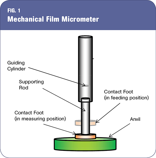
Mechanical film micrometers are constructed with a fixed anvil and a moveable contact foot. For film applications, the moveable contact foot usually has a flat surface.
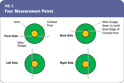
The anvil and flat surface of the contact foot must be parallel to within 1 micron (0.04 mils) to maintain accurate resolution for most mechanical micrometers. A parallelism wire gauge between the contact foot and anvil is required for this test. Maximum distance from the outside edge of the contact foot to the wire gauge should be no more than 3 mm (1/8 in.) in four directions, as shown.


Almost every film extrusion facility has mechanical devices to measure gauge variation. In many cases, the results differ from one device to the next, making it difficult to ascertain which one is correct. Operators need accurate information during setup to make sure the film gauge is within tolerance. They often overcompensate, making the film too thick in the beginning of a production run, and then adjusting after the first set of rolls is weighed. This strategy reduces yield and profit margins.
A common strategy to compensate for unreliable film gauge micrometers is to estimate the average thickness using the weight of a measured surface area of film (basis-weight technique) or the weight of a roll and core. Accuracy is limited because of possible variations in surface area of the film, concentration of ingredients (especially masterbatches), weight of the core, and length of film on the roll. Assumptions about the density of the various ingredients may be inaccurate. When this strategy is used to estimate average film gauge, mechanical film micrometers are relegated to the task of measuring thickness variation, not average film thickness.


Mechanical film micrometers are constructed with a fixed anvil and a moveable contact foot (see Fig. 1). For film applications, the moveable contact foot usually has a flat surface. There are three common causes for errors: incorrect contact pressure, presence of dirt, and misalignment between the anvil and contact foot.
Simple mechanical film micrometers rely on gravity to apply the correct contact pressure between the anvil and contact foot. More advanced systems use air pressure to do the same thing. Too much contact pressure compresses the film, giving readings that are thinner than the actual film. Operators often pull the film to the next measuring point while the contact foot rests on the film surface. This practice can bend the supporting rod, causing it to stick within the guiding cylinder. This will result in insufficient contact pressure, resulting in thicker-than-actual readings. In extreme cases, the contact foot cannot hold the film in position when it is lowered to the measuring position.
CLEANING & RECALIBRATION
Extrusion and converting facilities are dusty environments. Film-thickness micrometers are precision instruments that can detect the presence of dust and provide inconsistent measurements. Operators often resort to measuring the same point two or three times, a technique known as “stamping,” to obtain consistent thickness readings. This takes extra time and can compress the film, resulting in thinner-than-actual readings.
To clean the measuring surfaces, insert a piece of paper between the anvil and the contact foot. Then allow the contact foot to press the paper against the anvil, as if to measure the paper thickness. Pull the paper slowly about 5 cm (2 in.) while the contact foot is in the measuring position. Raise the contact foot and remove the paper. Bring the contact foot into contact with the anvil and recalibrate the micrometer to display zero thickness. Test the accuracy by raising and lowering the contact foot three or four times.
Measurement results should be between 0 and ±1 micron (±0.04 mils). If results vary more than this amount, try cleaning the measuring surfaces with a cotton swab soaked in alcohol and repeat the recalibration procedure. If measurement error persists, perform the parallelism procedure described in the next section.
PARALLEISM TEST & ADJUSTMENT
The anvil and flat surface of the contact foot must be parallel to within 1 micron (0.04 mils) to maintain accurate resolution for most mechanical micrometers. A parallelism wire gauge of 0.25 to 0.50 mm (0.01 to 0.02 in.) diam. is required for this test. If the instrument has a digital display, turn it on and wait at least 30 minutes for it to warm up before you begin.
Place the wire gauge on the anvil and lower the contact foot using standard pressure. The distance from the outside edge of the contact foot to the wire gauge should be no more than 3 mm (1/8 in.). Compare the measurements in all four positions as shown in Fig. 2. The film micrometer must be adjusted if the difference between opposite sides (front vs. back, left vs. right) is more than 1 micron (0.04 mils).
Some film micrometers have anvils that can be accurately repositioned. Another option is to use very fine sandpaper to make the measuring surface of the contact foot parallel to the anvil. This technique is known as lapping. Bent supporting rods cannot be repaired and must be replaced.
One point of view is that accurate measurement of film-gauge variations is not important because gauge variation cannot be eliminated, only tolerated. Companies that follow this strategy are doomed to low margins because they give away raw material.


Related Content

Troubleshooting Screw and Barrel Wear in Extrusion
Extruder screws and barrels will wear over time. If you are seeing a reduction in specific rate and higher discharge temperatures, wear is the likely culprit.
Read More
Fully Automated Extrusion Process Enables Use of Composites for Manufacturing Pressure Tanks
Amtrol was looking for a more cost-effective means to produce thin-wall liners for a new line of pressure tanks. With the help of a team of suppliers, they built one of the world’s most sophisticated extrusion lines.
Read More
Understanding the ‘Science’ of Color
And as with all sciences, there are fundamentals that must be considered to do color right. Here’s a helpful start.
Read More
How to Estimate and Control Head Pressure
You rightfully worry about melt temperature, but don’t overlook head pressure, because the two are closely linked and will influence line performance.
Read MoreRead Next

Understanding Melting in Single-Screw Extruders
You can better visualize the melting process by “flipping” the observation point so that the barrel appears to be turning clockwise around a stationary screw.
Read More
Why (and What) You Need to Dry
Other than polyolefins, almost every other polymer exhibits some level of polarity and therefore can absorb a certain amount of moisture from the atmosphere. Here’s a look at some of these materials, and what needs to be done to dry them.
Read More
Processor Turns to AI to Help Keep Machines Humming
At captive processor McConkey, a new generation of artificial intelligence models, highlighted by ChatGPT, is helping it wade through the shortage of skilled labor and keep its production lines churning out good parts.
Read More