
Don’t Just Be a ‘Replacer’
To be a skilled troubleshooter is about understanding how your molds function, paying attention to the details, establishing a consistent troubleshooting method, and using historical data to guide your tooling replacement decisions
A skilled troubleshooter saves his plant thousands of dollars in premature tooling replacement by determining exact locations and types of defects and their causes, rather than just “replacing everything” to make the mold run better.
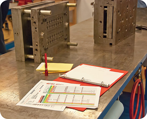
Be sure to document in your maintenance system exactly which piece of tooling you replaced to repair which defect. This is necessary to allow a “Corrective Action Analysis” report to discover and target high-cost defects.


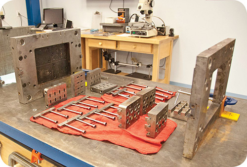
The repair technician walks over to the cabinets where tens of thousands of dollars’ worth of mold tooling were stored. Most of the bins are numbered with the appropriate component part number and a manual “check out” sheet hung close by to record what was taken. The technician, under the gun and in a hurry to get his mold back into production, plays the “drawer game” until he finds the tooling he needs to complete the job. After he has secured $3000 or $4000 worth of tooling, he heads back to his bench to install it and reassemble the mold.
When the job is complete, he sends the mold back to production. It starts up running 100% and everyone is happy—a job well done. But was it? Just because the mold started and ran at 100% efficiency, does that mean that the repair was efficient or that the tooling replaced was really at the end of its useful life? What is “useful life,” and how can we tell? What was done with the “old” tooling? Was it pitched or thrown on a shelf or into a “limbo” cabinet?


To better understand the corrective-action choices that a repair technician faces every day, it is necessary to look at the decision process typically used to determine what tooling to replace—or not.
TYPICAL TROUBLESHOOTING PROCESS
There are basically two categories of defects that repair technicians have to contend with. They are mold function issues that don’t directly affect the part, and tooling issues that do affect the part geometry. For this article we will focus on the latter—product-type defects, or those that affect product specifications such as flash, shorts, finish, etc. For this repair scenario we will assume that the repair technician has, according to the hand-written Work Order he received, disassembled the multi-cavity mold and marked up a cavity layout sheet that shows the location of the cavities that have flash over the specification limit. These are the next steps:
1) Examine the defective part samples to determine the exact location of the flash.
2) Determine exactly which pieces of tooling could be causing the flash (core, sleeve, cavity, etc.).
3) Remove and examine the tooling in the area that forms the flashed area of the part.
4) If nothing is obvious (chips, nicks, scuffs, etc.), go to the tool crib and pull drawers until you find the tooling you need.
5) Measure the tooling and compare with print tolerances. If within print specifications, replace. (This is optional for some and mandatory for others.)
6) Install the tooling in the mold and complete the repair.
The above steps are what could be expected of a “tooling replacer” vs. a skilled troubleshooter. There are several things the replacer does not do within these steps to ensure that the decision to replace is the correct one.
Let’s re-examine these steps from a troubleshooter’s perspective to see what was missed and why those missed steps are critical to maximize the life expectancy of mold tooling and the reliability of mold performance, and also to improve our ability to accurately determine root causes and corrective actions.
1) Examine the defective sample parts to determine the exact location of the flash on the part. Actually, it’s more than just the “location” of the flash on the part that must be considered. (Molders take note: This is why samples of defective parts are so important.) The “direction” of the flash must also be known. For example, “vertical” flash is usually the result of an excess of plastic between a core and a sleeve or any tooling where clearance is determined by a running fit. “Horizontal” flash is usually the result of excess plastic between two shutoffs, such as “A” and “B” plate cavity faces or tooling where “preload” (total tooling stack) or clamp pressure and other shut-off factors affect clearance. These two types of flash must be distinguished by the appropriate defect term, since their root causes, and thus corrective actions, can be completely different.
This is a good example of why typical Work Order records that show only the defect term “flash” won’t do. Mold design features that cause ongoing flash issues must be recognized in order to be eliminated or reduced when the next mold is built. When repair technicians are pushed to get a mold back into the press, sometimes “shop culture” will allow this tooling to be replaced just because it’s in stock. No big deal, right? Yes, it is. Premature replacement causes us to miss the opportunity to understand and define the variables that actually create our defects. This is a skill that needs to be continually developed because continuous improvement is about improving our ability to accurately determine if any given defect is caused by mold design, process, maintenance issue, or a combination of all three.
2) Determine exactly which pieces of tooling could be causing the flash (core, sleeve, cavity, etc.): The more complex the part, the more difficult to eject it from the mold due to threads, undercuts, bores, bosses, etc. This typically means that more tooling is needed to shape such a part. A mold could easily have three, four, or more pieces of tooling to mold an edge or other feature on a part.
But not all of these will be worn to the point of causing the flash. Some mold designers take this into consideration when designing a mold, and will have less expensive pieces designed to wear first, to lessen the cost of repair. Maintenance history will confirm or deny the success of the design approach used.
All defects should also be recorded and tracked by mold position so that one can look for patterns or trends that can point to insufficient cooling, heating, or runner/flow balance, as well as gate and venting issues and other process-related root causes.
Not doing so is a huge mistake and can lengthen the time required to discover a root cause. Mold position numbers never change and should be stamped, etched, or ground into plates and tooling so that components get put back into their “home” positions.
3) Remove and examine the tooling that forms the flashed area of the part: Here is another area where the troubleshooter is differentiated from a tooling replacer. First, if two or more parts (cavity positions) have the exact same defect, it always pays to examine the tooling all at the same time vs. skipping around the mold in, say, a clockwise fashion (many do this), analyzing and correcting different defects as you go.
Second, don’t just grab your micrometers, measure the tooling, and assume it’s bad if it’s under print dimensions. There are hundreds of thousands of tooling components that make perfectly acceptable parts (within QA specifications) and are 0.001, 0.002, or 0.003 in. under print tolerances. Print tolerances should be a factor in replacement decisions—not the decider.
Third, develop a standard method to examine tooling, such as the following:
a) Remove the suspect tooling from the mold and make sure all pieces are numbered correctly to their home position.
b) Go to the tool crib and get one piece of new/replacement tooling that matches what you removed.
c) Grab the defective parts, old tooling, and new tooling and head to your good-quality stereo microscope.
d) Orient the tooling in the manner that it fits together in the mold.
Set the power on the scope to 10 for most parts—unless you micro-mold, then higher power is needed. Why 10 power? Typically you will be looking for clearances between tooling that ranges from 0.0005 to 0.005 in. A 0.001-in. gap between tooling looks like the Grand Canyon at anything much over 10 power, which can make a good running fit appear as if it should be flashing. Stay with 10 power as much as possible in everything you do and you will get very good at accurately judging good running fits vs. those with too much clearance. Be consistent in your microscope practices and you will soon recognize the difference between tooling fits with acceptable clearance and the other kind. (Note: Well equipped shops have scopes for each repair technician.)
Compare the mated tooling to the area of flash on the part, being aware of flash direction, length, and thickness. After you have found the area of tooling that is flashing, make a mental note of the clearance between the tooling. Now replace one of the suspect tooling components with a new piece and re-examine the clearance. Does it look smaller or stay the same? If it’s a dynamic fit (core vs. sleeve), does it feel the same? Tighter? Still loose?
Interchange new tooling with old (this takes only a few minutes) to determine which piece of tooling has the most influence on increasing the clearance between the two or more pieces of tooling that form the flashed area. Continue with this method until you have chosen which tooling you want to replace on all similar defects.
This method should not take longer than a few minutes per defect to accurately determine what needs to be replaced. Even if troubleshooting 10 defects took an extra hour or two, it would be much more cost-effective to spend the time on labor vs. the extra thousands of dollars you will spend to replace tooling before its useful life has expired. In addition, we will learn more about our mold’s defects.
6) Install the tooling and document the repair: When satisfied, inscribe (using a small Dremel grinder and stone) the position number onto the tooling you want to replace. This will help avoid any mix-ups in future repairs. Be sure to document in your maintenance system exactly which piece of tooling you replaced to repair which defect. This is necessary to allow a “Corrective Action Analysis” report to discover and target high-cost defects.
Such documentation is also needed so repair technicians can get better at “forecasting” tooling wear over time, and to verify that the correct piece of tooling was chosen for replacement. The right choice will not always be made the first time, and there will be times when it is absolutely necessary to replace everything in sight to ensure a mold runs 100% for long production runs (months). But you will still have an opportunity to save your plant thousands of dollars in premature tooling replacement by using the above techniques vs. “just replace everything” as a corrective-action resolution.
This is the true skill in troubleshooting. A repair technician that practices this technique will get very good at determining which piece of tooling to replace vs. replacing everything that could possibly cause the flash. Anybody can be a “replacer.” To be a skilled troubleshooter is about understanding how your molds function, paying attention to the details, establishing a consistent troubleshooting method, and using historical data to guide your tooling replacement decisions.


Related Content

Optimizing Pack & Hold Times for Hot-Runner & Valve-Gated Molds
Using scientific procedures will help you put an end to all that time-consuming trial and error. Part 1 of 2.
Read More
Back to Basics on Mold Venting (Part 1)
Here’s what you need to know to improve the quality of your parts and to protect your molds.
Read More
Back to Basics on Mold Venting (Part 2: Shape, Dimensions, Details)
Here’s how to get the most out of your stationary mold vents.
Read More
Best Methods of Molding Undercuts
Producing plastics parts with undercuts presents distinct challenges for molders.
Read MoreRead Next

Lead the Conversation, Change the Conversation
Coverage of single-use plastics can be both misleading and demoralizing. Here are 10 tips for changing the perception of the plastics industry at your company and in your community.
Read More
Advanced Recycling: Beyond Pyrolysis
Consumer-product brand owners increasingly see advanced chemical recycling as a necessary complement to mechanical recycling if they are to meet ambitious goals for a circular economy in the next decade. Dozens of technology providers are developing new technologies to overcome the limitations of existing pyrolysis methods and to commercialize various alternative approaches to chemical recycling of plastics.
Read More
Processor Turns to AI to Help Keep Machines Humming
At captive processor McConkey, a new generation of artificial intelligence models, highlighted by ChatGPT, is helping it wade through the shortage of skilled labor and keep its production lines churning out good parts.
Read More