
Energy Miser: Plug Costly Compressed-Air Leaks
Last month we introduced the idea that compressed-air usage is one of the first places any manufacturer should look to reduce energy cost.
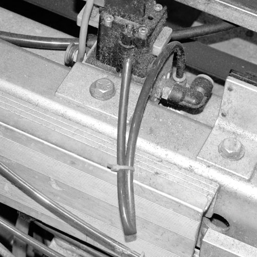
Common ways of terminating compressed air lines. None of these methods is acceptable! Electrical fitters use cable ties.
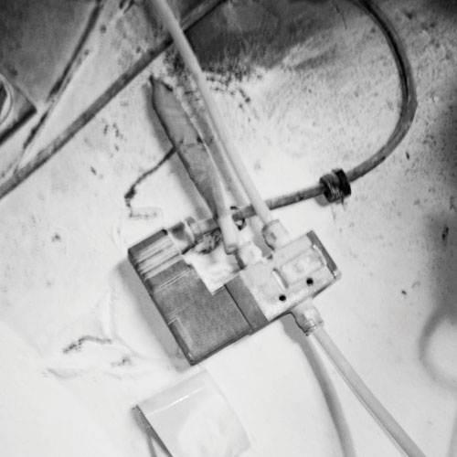
Mechanical fitters use adhesive tape.
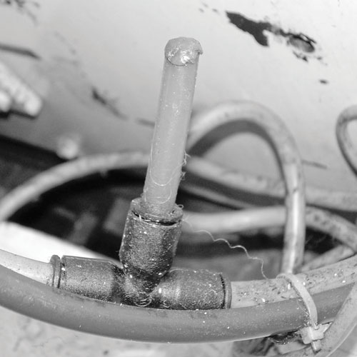
Smokers use a cigarette lighter.
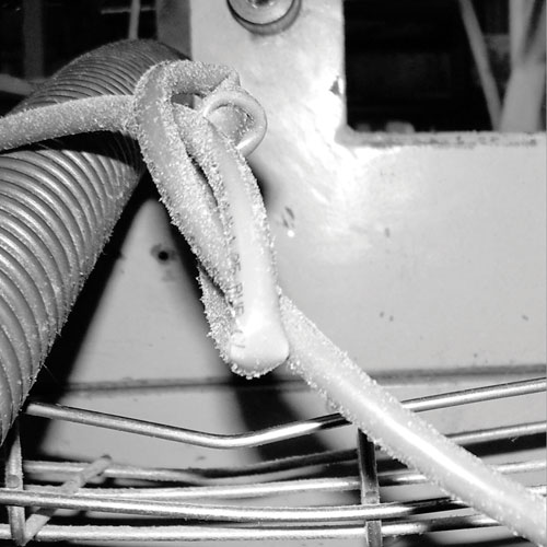
Operators use anything.


Last month we introduced the idea that compressed-air usage is one of the first places any manufacturer should look to reduce energy cost. That’s because compressed air is expensive; it is often wasted; curtailing that waste is both quickly and easily accomplished; and the gains are easy to quantify. Now let’s look at where all that money is disappearing into thin air.


THE INVISIBLE COST
Reducing leakage is the first step in minimizing compressed-air demand. In plastics processing, typical leakage rates are of the order of 30% to 50% with an approximate average of 40%. That is, 40% of the compressed-air generating power (forty percent!) is wasted through leaks in the distribution system. Every system will have leaks, and target “acceptable” leakage rates vary with the plant size:
- For small plants the leakage should be from 5% to 7%.
- For medium plants the leakage should be from 7% to 10%.
- For large plants the leakage should be from 10% to 12%.
Most plastics processing plants fall into “medium” category and should aim for a leakage rate of 7% to 10%. This means that the average site could save approximately 30% of the cost of compressed air by achieving the target leakage rate.
Leakage is not only a direct source of waste; it is also an indirect contributor to operating costs. As leaks increase, the system pressure drops and the most common solution is to increase the pressure to compensate for the losses. Extra generating pressure costs more money.
The first step in leakage reduction is to recognize the costs involved and make a commitment to a plant awareness program. Regular, continuous attention to the compressed-air system, coupled with proper maintenance, will lead to progress in minimizing leaks.
‘SSSSS’: SOUND OF MONEY ESCAPING
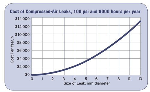
The cost of a given leak (in terms of equivalent mm diameter) at a pressure of 100 psi operating for 8000 hr/yr is shown in the accompanying graph. A 3-mm hole in a system at 100 psi will cost around $1300 per year in generation costs. In a system with numerous leaks, this cost will multiply rapidly. The lower limit for an audible leak is in the region of $130/yr. That means that if the plant is not operating and is quiet then any leak you can hear will be costing you a minimum of $130 per year. That ‘ssssss’ noise you hear is not a normal operating condition; it is energy and money being wasted. The cost of a given leak will be even greater if the system is running at a pressure of greater than 7 bar (100 psi) or for longer than 8000 operating hours.
CONDUCT A LEAKAGE SURVEY
Simple leakage surveys and maintenance can produce dramatic cost reductions. In some cases, leak reporting and repair has enabled companies to shut down some compressors for all or most of their operating time.
A leak detection program should be established to survey the plant regularly to detect leaks and fix them. Surveys can be made by finding audible leaks during a shutdown period, using a solution of soap and water to find leaks during normal operation, or by using an ultrasonic detector at any time. Compressed-air leakage control is not a single task that can ever be completed; it is a continuous rolling program of leak detection and sealing that never ends.
We advise using an ultrasonic detector and a program of 2 hr per week for detection and rectification of leaks in specific areas. Find a leak, tag it, and seal it.
LEAKAGE MEASUREMENT
It is possible to carry out actual measurement of system leakage only when all of the equipment that normally uses compressed air is completely shut down. This means that measurement must be outside normal operating hours, a difficult thing to do when running 24/7. Here are two methods.
Cycle timing method:
- Shut down all air-operated equipment.
- Start the compressor. After the mains and receivers have reached the setpoint, the compressor will switch off. As air leaks cause the pressure to fall below the setpoint it will switch on again.
- Record the average on-load time (T) and average off-load time (t) over a minimum of at least 5 cycles.
- Establish the compressor delivery capacity Q (in cu ft/min) from the nameplate or other documentation.
- Calculate total leakage from T, t, and Q: Leakage = Q x T/(T+t)
If the compressor capacity is not known, then this method can provide an estimate of the leakage as a percentage of the total compressor capacity.
Pressure decay method:
This method can be used if the compressor delivery capacity (Q) is not known or if it is a modulating compressor. This is not as accurate as the cycle timing method at low pressures, such as 100 psi, but is sometimes the only method available:
- Calculate the volume of the compressed-air distribution system (V) in cu ft. This should include the volume of all piping over 1 in. diam. and all receivers.
- Pump up the system to the setpoint (P1) as recorded on the receiver pressure gauge.
- Isolate the receiver and the system from the compressor.
- Using an accurate pressure gauge, record the time (T) for the pressure to drop to P2 (at least 30 psi below P1) over a minimum of at least 5 tests.
- Calculate the total leakage: Leakage = V x (P1 - P2)/T
- Redundant spurs in the system.
- Condensate traps.
- Aging pipework.
- Fittings and flanges. Leaks are caused by pipe strain due to inadequate supports, inadequate joints, or twisting.
- Flexible hoses. Leaks can be caused by abrasion, deterioration (e.g., from heat sources), or mechanical impact. Use permanent fixings rather than worm-drive fixings.
- Regulators. These are often a source of leakage and abuse by operators. Check all regulators for correct setting and operation, and replace as required.
WHERE TO LOOK FOR LEAKS
Use a Compressed Air Map to plan your leakage survey. Keep a record of where you fixed leaks last time—leaks often occur in the same places. Here are typical culprits:
Isolate machinery, supply lines, even whole buildings, from the compressed-air mains when not in production. This can be done automatically using electronic controllers.
FEEDING ITSELF
During an energy survey, it was once discovered that the plant’s substantial compressor system was doing nothing but feeding the leaks. The system was maintained and was being paid for, but the compressed air was not actually being used for anything. The only consumer of compressed air was the leakage of the system itself!
We turned it off.
Next installment: Compressed-air usage reduction.
About the Author
Dr Robin Kent is founder and managing director of Tangram Technology Ltd. in Hitchin, Herts., U.K. Tangram provides consulting and training in plastics engineering and design. Kent has 36 years’ experience in injection molding and extrusion as technical director for several processing companies in Europe. Articles in this series are adapted from Energy Management in Plastics Processing (2008, 265 pages, pidbooks.com). Contact rkent@tangram.co.uk or visit tangram.co.uk.


Related Content

Use Interactive Production Scheduling to Improve Your Plant's Efficiencies
When evaluating ERP solutions, consider the power of interactive production scheduling to effectively plan and allocate primary and secondary equipment, materials and resources on the overall production capacity of the business and conclude that this is a key area that cannot be overlooked.
Read More
Solve Four Common Problems in PET Stretch-Blow Molding
Here’s a quick guide to fixing four nettlesome problems in processing PET bottles.
Read More
Mold Opaque White PET Bottles – Without Pigment
Trexel and Husky are cooperating on molding recyclable opaque white preforms for PET bottles, which provide a light barrier using foam instead of pigment.
Read More
Get Color Changes Right In Extrusion Blow Molding
Follow these best practices to minimize loss of time, material and labor during color changes in molding containers from bottles to jerrycans. The authors explore what this means for each step of the process, from raw-material infeed to handling and reprocessing tails and trim.
Read MoreRead Next

Understanding Melting in Single-Screw Extruders
You can better visualize the melting process by “flipping” the observation point so that the barrel appears to be turning clockwise around a stationary screw.
Read More
How Polymer Melts in Single-Screw Extruders
Understanding how polymer melts in a single-screw extruder could help you optimize your screw design to eliminate defect-causing solid polymer fragments.
Read More
People 4.0 – How to Get Buy-In from Your Staff for Industry 4.0 Systems
Implementing a production monitoring system as the foundation of a ‘smart factory’ is about integrating people with new technology as much as it is about integrating machines and computers. Here are tips from a company that has gone through the process.
Read More