Extrusion: A Simple Way to Evaluate Your Screw Performance, Part 2
A hand-held calculator and some basic equations can help determine whether your screw is up to snuff.
Single-screw performance is one of the most critical but least understood factors in processing. To be an expert takes some very specialized training and experience. However, to understand the basics of single-screw performance requires only a simple hand-held calculator.
In June’s column, we simplified extruder screw output using the dragflow equation for a screw having a standard-pitch metering section. The calculation was simplified to:
0.02258 (D2)HN = Output (in.3/sec)
Where:
D = Screw diameter, in.
H = Channel depth, in.
N = Screw rpm
The result (in.3/sec) can be converted to lb/hr by multiplying 130 x melt specific gravity of the polymer. In June, we also showed the full formula if the pitch is other than standard. With these calculations, remember that these outputs are for open discharge or no head pressure.
When I’m asked to evaluate the performance of a screw, the first thing I do is see how its actual performance stacks up to its calculated drag flow. It’s unusual for a screw to significantly exceed the calculated drag flow unless the metering section is very short or the feed section is grooved. So, the calculated drag flow is generally the maximum output that would be expected.
If the actual output is very close to the calculated and is stable, you can assume the screw has a balanced design. That is, the feed, melting and pumping sections are all working properly to achieve output of the metering section. If the output is well under the drag flow, then there is a series of things to check and the first is the effect of the head pressure. When there is head pressure—as in an actual extrusion operation—the output is generally less than the drag flow.
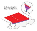
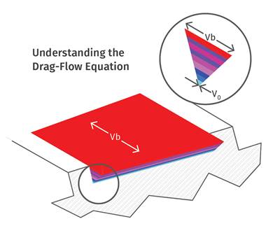
In the accompanying illustration, A shows pure drag flow where the velocity at the top of the channel equals the velocity of the barrel relative to the screw and the bottom is zero velocity as the resin is stuck to the screw; while B shows the effect of head pressure. The drag flow is still there, but the head pressure is causing a backward flow near the bottom of the channel. The net flow is a combination of the drag flow minus the pressure flow.
The effect of head pressure is a less exact calculation than the drag flow for several reasons. First, it depends on the polymer viscosity in the metering section; and second, there is usually a pressure at the beginning of the metering section that can offset the head pressure just like two pressures in a pipe. Neither of these variables is easy to determine precisely, even with advanced computer simulation.
As a result, pressure flow is an estimate based on a viscosity from shear-rate/viscosity curves at the specific melt temperature, and an assumption of the pressure at the beginning of the metering section. Estimation of the viscosity can be pretty accurate if you know the exiting melt temperature and have the shear-rate/viscosity data for that polymer. Estimation of the pressure at the beginning of the metering section, on the other hand, involves quite a few variables and takes experience.
Pressure development in the screw is proportional to the screw speed, section length, viscosity, flight pitch, and diameter; and is inversely proportional to the square of the channel depth. Even with considerable experience, it’s difficult to determine much more than an approximation of the pressure entering the metering section without pressure transducers placed along the barrel. As a result, it’s typically ignored and the discharge or head pressure is used to calculate the pressure flow.
The calculation for the effect of head pressure is again based on the work done at Western Electric in the 1950s and is still widely used today:
Fpπ D H3 P W (sin Θ)2/(12Lμ) = Pressure flow
For most screws, W (percent of channel) is 0.9 or 90%, since most flights are 10% of the pitch; and Fp is 1.10 for standard pitch, except for very deep screw channels, essentially cancelling each other.
This, then, simplifies the equation to:
π D H3 P (sin Θ)2/(12Lμ) or 0.02163 D H3 P/Lμ
Where:
D = screw diameter, in.
H = Channel depth, in.
P = Head or discharge pressure, psi
L = Metering-section length, in.
μ = Viscosity, lb-sec/in.2
Since most viscosity data is expressed in PaS or poise it can be converted by:
1 poise = 0.0000145 lb-sec/in.2 and 10 poise = 1 PaS
Then the other terms can be in English units.
As an example of how to use this, let’s take a 3.5-in. screw turning at 100 rpm with a head pressure of 30 psi. The screw has a standard pitch (3.5) and standard flight width (0.35 in.); the metering length is 30 in., and the channel depth is 0.150 in. The viscosity is 10,000 poise at the shear rate in the channel and the discharge temperature.
So:
(0.02258) D2H N-(02163) D H3 P/Lμ = Net output, in.3/sec 4.149-0.176 = 3.973 in.3 /sec
Multiply by 130 x melt specific gravity for LDPE:
3.973 x 130 x 0.75 = 387.4 lb/hr
The complete formula shown above can be used where the flight pitch, flight width and Fp are greater due to exceptionally deep channels.
In this example, the actual screw output was 375 lb/hr. That’s close enough to the calculation that you can assume the screw is performing basically as it should for this application. However, if the actual output is, say, 250 lb/hr, then there is something causing the screw to perform below its calculated net flow. It could be a feeding issue, a melting issue, or poor screw design for the particular polymer, resulting in a screw design that is not balanced throughout.
ABOUT THE AUTHOR: Jim Frankland is a mechanical engineer who has been involved in all types of extrusion processing for more than 40 years. He is now president of Frankland Plastics Consulting, LLC. Contact jim.frankland@comcast.net or (724)651-9196.
Related Content
The Effects of Temperature
The polymers we work with follow the same principles as the body: the hotter the environment becomes, the less performance we can expect.
Read MoreA Simpler Way to Calculate Shot Size vs. Barrel Capacity
Let’s take another look at this seemingly dull but oh-so-crucial topic.
Read MoreWhy (and What) You Need to Dry
Other than polyolefins, almost every other polymer exhibits some level of polarity and therefore can absorb a certain amount of moisture from the atmosphere. Here’s a look at some of these materials, and what needs to be done to dry them.
Read MoreHow to Set Barrel Zone Temps in Injection Molding
Start by picking a target melt temperature, and double-check data sheets for the resin supplier’s recommendations. Now for the rest...
Read MoreRead Next
Extrusion: A Simple Way to Evaluate Extruder Screws
While there’s lots of data that influences screw design, processors usually don’t have access to it. So instead, try calculating drag flow to see if your screw is working properly.
Read MoreProcessor Turns to AI to Help Keep Machines Humming
At captive processor McConkey, a new generation of artificial intelligence models, highlighted by ChatGPT, is helping it wade through the shortage of skilled labor and keep its production lines churning out good parts.
Read MoreHow Polymer Melts in Single-Screw Extruders
Understanding how polymer melts in a single-screw extruder could help you optimize your screw design to eliminate defect-causing solid polymer fragments.
Read More.jpg;width=70;height=70;mode=crop)
