How to Estimate and Control Head Pressure
You rightfully worry about melt temperature, but don’t overlook head pressure, because the two are closely linked and will influence line performance.
.jpg;width=70;height=70;mode=crop;format=webp)


Head pressure never seems to be a big concern of extrusion processors, while melt temperature is something that always worries them. But they are closely connected. The melt temperature at open discharge is a function of the extruder alone; it is controlled by the screw design, screw speed, L/D ratio, polymer properties, condition of screw and barrel, and efficiency of barrel heating/cooling. That becomes a baseline temperature that can be altered only with changes in one or more of those extruder variables.
When head pressure is applied to the end of the extruder, the melt temperature rises non-linearly from the baseline with increasing pressure. That’s due to a cascading effect of the pressure flow—output from the screw is reduced as the head pressure increases. As the screw continues to rotate with reduced output, the energy via shear stress going into the polymer is increasing. The increasing energy input results in an increase in the melt temperature and a decrease in the viscosity of the polymer, further increasing the pressure flow and further decreasing the output.


Head pressure further increases the melt temperature from the extruder baseline.
Effect on Outcomes
So, melt temperature is connected to head pressure and results in reduced output, greater power requirement, more downstream cooling, and maybe even degradation of the polymer properties. This results in greater manufacturing cost and needlessly compromises the performance of whole systems when it is easily diagnosed and corrected.
A melt pump can correct much of this effect by allowing a head pressure that is usually much lower than the full head pressure. However, many processes cannot tolerate use of a melt pump due to the incorporation of fillers and the possibilities of polymer degradation and contamination. In those applications, the downstream tooling design is important to the performance and profitability of the line. Unfortunately, there is often no consideration of the effects of head pressure in the selection of the downstream components and its effect on the overall process.
Head pressure can be accurately estimated and controlled by proper design. This involves mostly simple things, such as limiting the length of adapters and flow pipes, proper sizing of the screen changer, die designs specific to the polymer properties, proper sizing of all the flow channels for the expected output, and proper heating of the downstream components.
Flow Channel Design
The simplest forms of flow channels are the circle, slit and annulus. There are simple approximations for calculating each of these basic shapes. By using basic Newtonian formulas for each shape, you can illustrate the principles and get a good estimate of the head pressure (see accompanying table and Figure 1). Using Newtonian equations requires determining the viscosity from shear-rate/viscosity curves for that polymer at the appropriate temperature. Newtonian analysis neglects some viscoelastic effects—like viscous heating at the wall and entrance effects as the flow shapes change. The shear rate must be calculated and then applied to the shear-rate/viscosity curves at the processing temperature to obtain the correct viscosity. As a result, these are approximate values, adequate for equipment selection, and they show the effect of the important variables to give the processor the knowledge for analysis without benefit of a more rigorous computer analysis.
There is often no consideration of the effects of head pressure in the selection of the downstream components and its effect on the overall process.
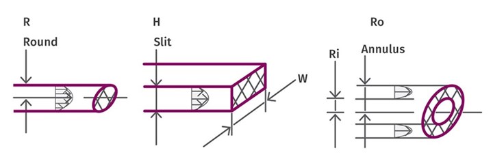
Fig. 1 Pressure is dependent upon flow rate and the geometry of the flow channel.
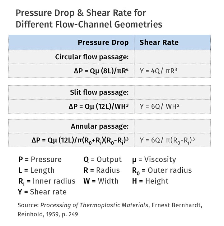
As you can see from the table, for a round channel, the pressure is increased by eight times the length but decreased by the fourth power of the radius. For a slit channel , the pressure is increased by 12 times the length and decreased by the width and the cube of the height. For an annular channel the pressure is increased by 12 times the length and decreased by the cube of the difference in the radii. So, to minimize head pressure, flow passages should be as short as possible and as large as possible. However, “as large as possible” has a definite restriction.
Keeping Channel Walls Clear
To clean the walls of the passage (not get scale or a static layer on the walls), the shear stress at the wall needs to be great enough to provide continuous renewal of the material near the wall (see Figure 2).
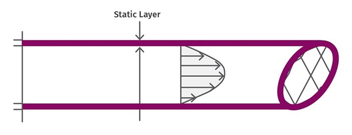
Fig. 2 The shear stress at the wall needs to be great enough to provide continuous renewal of the material near the wall to avoid getting a scale or static layer on the walls. Tooling designers have their preferences, but 10 psi is typical.
Different levels of stress are preferred by different tooling designers, but 10 psi is typical. Too low a shear stress at the wall builds temperature differentials into the extrudate from large differences in residence time and will cause unstable flow.
It may even cause degradation of the layer on the wall with thermally sensitive polymers. Shear stress at the wall is a simple formula but depends on the pressure drop, as calculated below:
Shear stress at wall= ΔP•R/2L
L is either the radius of a circular orifice, or the gap between the slit opening (H) or the gap in an annular die (R0-Ri). Proper heating of the downstream tooling is an important part of controlling head pressure. The tooling temperatures should be kept as close to the melt temperature as possible. That prevents developing the scale or static layer of colder, more viscous polymer on the inner walls that simply narrows the flow passage and causes increased pressure drop. It’s difficult to reduce melt temperature by cooling the tooling because of its effect on raising the head pressure and because of the low thermal conductivity of the polymer.
When assembling an extrusion line for any new shape, the estimation of head pressure from the tooling should be considered in the output and cooling calculations. That’s done by minimizing the length of the flow passages and holding the wall shear stress to as close to 10 psi as possible by adjusting the size of the flow passage.
ABOUT THE AUTHOR: Jim Frankland is a mechanical engineer who has been involved in all types of extrusion processing for more than 50 years. He is now president of Frankland Plastics Consulting, LLC. Contact jim.frankland@comcast.net or (724) 651-9196.
Related Content

A Simpler Way to Calculate Shot Size vs. Barrel Capacity
Let’s take another look at this seemingly dull but oh-so-crucial topic.
Read More
Understanding Strain-Rate Sensitivity In Polymers
Material behavior is fundamentally determined by the equivalence of time and temperature. But that principle tends to be lost on processors and designers. Here’s some guidance.
Read More
How to Stop Flash
Flashing of a part can occur for several reasons—from variations in the process or material to tooling trouble.
Read More
Tunnel Gates for Mold Designers, Part 1
Of all the gate types, tunnel gates are the most misunderstood. Here’s what you need to know to choose the best design for your application.
Read MoreRead Next

How Polymer Melts in Single-Screw Extruders
Understanding how polymer melts in a single-screw extruder could help you optimize your screw design to eliminate defect-causing solid polymer fragments.
Read More
Lead the Conversation, Change the Conversation
Coverage of single-use plastics can be both misleading and demoralizing. Here are 10 tips for changing the perception of the plastics industry at your company and in your community.
Read More