
Flow Analysis Gets It Right the First Time
This molder's trial parts showed visible flaws that made them unusable. Simple changes in tooling, processing, or materials couldn't fix it. But flow simulation provided an answer that worked right off the bat.

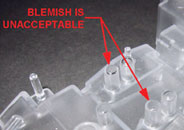
Fig. 1—Trial parts of this polycarbonate component of electronic bill-handling equipment had blemishes at the tips of two bosses that must be clear, smooth windows for optical sensors behind the bosses.
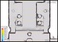
Fig. 2—The simulation program’s default display of 40 flow contour lines per model does not provide enough detail in the critical boss area to indicate any filling problem.
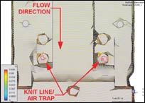
Fig. 3—Increasing the number of contour lines to 400 for the flow plot clearly reveals the knit line and air trap in the critical boss areas.
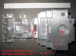
Fig. 4—Doubling the wall thickness in the center of the part created a “flow leader” that moved the knit line away from the critical boss.
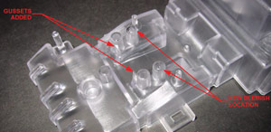
Fig. 5—Adding gussets completed the flow modification, which moved the blemish to a non-critical area.
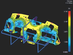
Fig. 6—A new flow analysis shows the movement of the air trap to the first row of bosses, which serve no optical function.
Coin Acceptors Inc., a leading manufacturer of electronic coin and bill handling equipment, produces a wide range of plastic parts from engineering resins. Initial samples of a new clear polycarbonate part showed processing defects that threatened the success of an entire project. Using flow-analysis software allowed us to solve this problem on the first try. This not only saved tooling costs and the project schedule, but allowed the electronic system to operate perfectly.


Diagnosing the problem
Before we could find a solution, we had to know exactly what was going on with this part. The problem was due to a flow bubble and knit line forming on the surface of a boss that was being used as a transparent surface for an optical sensor (see Fig. 1). Surface imperfections on the optical area caused poor performance of the electronic component. Viewing the area under high magnification revealed “orange peel” and a void or fold in the area.
We routinely perform a flow analysis on all our new parts. We typically use shaded solid plots to review the pattern of melt-front advancement during filling. In this case, the wall thickness of the PC part was 0.060 in., which was thinner than most of the parts we make. However, the flow analysis indicated it would fill just fine. Weld lines are not normally a problem in our parts, so a cursory look at the fill plot usually suffices.
After the trial parts indicated a problem, my first thought was to review the simulation I did prior to the tool build to see if the software had predicted this knit line. If the original analysis did not show the knit line here, I would not be able to use the flow-analysis software to solve the problem.
The shaded image I had used originally did not provide enough detail in the critical boss area to see a problem. I then began to review the old simulation using contour plots instead. The software’s default setting is 40 contour lines per model. (In other words, it divides filling into 40 time segments.) That was too crude to indicate any problem either (Fig. 2). I was able to see finer and finer detail as I increased the number of contour lines. At 400 contour lines for the plot, the knit line in the critical boss area was revealed (Fig. 3). It showed up clearly as an air trap and knit line on the end of the boss exactly where the blemish was on the molded sample. (I have since found out that not all currently available flow-simulation software can provide so many contour lines.)
This was great! Now I had an electronic baseline simulation that matched the real part. This proved to me that I could experiment with the model on the computer with confidence that I could reproduce the results in the molding press.
The original melt-front plots showed that the material hesitated after the first boss was filled, causing an eddy and a knit line to form as the material reached the second boss.
What to do next?
Several ideas were discussed to resolve the problem. Our processing engineer tried changing the process parameters to improve flow. Several variations were attempted, including faster and slower fill times and adjusting the temperature profiles. These attempts showed no consistent solution in the problem area. Higher packing caused the parts to stick and the ejector pins pushed into the parts.
We considered adding a core pin in the problem area to improve venting and packing. Unfortunately, that approach could leave witness marks that would further reduce the optical and electrical performance. I had a low degree of confidence in this solution, since there was no burning of material here, and our analysis software indicated perfect venting.
Adding a bridge between the bosses to improve flow was discussed. Mating parts would need to be modified to allow this. These mating parts are used in other assemblies and would require extensive quality testing before the change could be implemented. Also, one of these changes would involve welding in a thin, deep area of the tool. Such tool modifications would be very expensive, time consuming, and risky.
Another idea was to change the way the material flowed into the problem bosses. Since this tool incorporated a hot sprue bushing, moving the gate location was out of the question. A different way to change the flow characteristics of a part would be to enhance or restrict the melt front. This could be done by increasing or reducing the wall thickness in strategic areas. We chose to pursue this idea as the best way to solve this problem.
Engineering a solution
In order to best position and size flow channels into the part, I immediately went to flow-analysis simulations. It was unrealistic to attempt this by trial and error. We would have had to make a small change to the tool, set it in the press, run a few samples to see the effect, then repeat the process until we got it right. Instead, I made the changes on the computer model, ran the analysis, and reviewed the results at my desk.
My initial modifications of the computer model were to increase the wall thickness of the first boss. This made no significant difference in the flow characteristics. The blemish did not move. Next, a narrow flow channel was created adjacent to the bosses to allow material to reach the farther boss quicker. This shifted the blemish to a different region of the optical surface.
These results proved the concept was sound, but a more drastic change was needed. Since the space in the center of the part was not being used, we decided to use the entire wall as a flow leader (Fig. 4). The nominal wall thickness was doubled from 0.060 in. to 0.120 in. on this wall and another simulation was launched. This time, a significant change showed up on the melt-front advancement plot. The distortion had moved to the edge of the optical area. This might have produced a satisfactory part, but we needed a better safety factor. In the final analysis, a gusset was added between the thick wall and the second boss. The result of this last detail was amazing: The blemish moved all the way back to the first boss, which serves no optical function (Figs. 5 & 6).
After the flow problem had been solved, a thorough review of the entire analysis was in order to make sure that other processing parameters had not been compromised. The cycle time had increased by about 2 sec as a result of the thicker wall sections—a small price to pay if the part works.
Armed with the flow analysis and computer model, the part was updated to the new dimensions. The modifications to solve the processing problem were sent to the tool room to update the mold. These changes were done at the same time that an assembly feature was incorporated into the part to further minimize downtime of the mold. After about two weeks, the tool was ready to be tried again.
Positive results
The first samples off the tool looked just like what the software had predicted. It turned out that our molding department was able to modify the temperatures and times to compensate for the added wall thickness without needing to increase the cycle time. The critical lens areas were smooth and distortion-free, and the parts were consistently clear over a wider processing window. Later testing on the completed units showed the electronic sensors operated at peak performance.
The real payoff here is often missed by managers and accounting personnel: It is difficult to place a dollar cost on the trial-and-error approach. The old way of attempting to fix a problem like this would have included many trips to the tool room and back to the press. Each time, the project schedule would slip a little more, the cost would go up, and the inserts to the tool get a little more degraded from welding, burning, and sub-inserting etc. The bottom line in this case is that using flow-analysis software gives us the confidence to make the right changes the first time out.


Related Content

How to Achieve Simulation Success, Part 2: Material Characterization
Depending on whether or not your chosen material is in the simulation database — and sometimes even if it is — analysts will have some important choices to make and factors to be aware of. Learn them here.
Read More
Take Time to Save Time: Five Steps in Mold Design to Reduce Back-End Troubleshooting
Westminster Tool shares how the one week it typically takes to perform these five steps in the design phase can save three weeks or more in an overall tool build.
Read More
50 Years of Headlines … Almost
I was lucky to get an early look at many of the past half-century’s exciting developments in plastics. Here’s a selection.
Read More
50 Years...600 Issues...and Still Counting
Matt Naitove marks his first half-century in plastics reporting, with a few of his favorite headlines.
Read MoreRead Next

How Polymer Melts in Single-Screw Extruders
Understanding how polymer melts in a single-screw extruder could help you optimize your screw design to eliminate defect-causing solid polymer fragments.
Read More
Why (and What) You Need to Dry
Other than polyolefins, almost every other polymer exhibits some level of polarity and therefore can absorb a certain amount of moisture from the atmosphere. Here’s a look at some of these materials, and what needs to be done to dry them.
Read More