

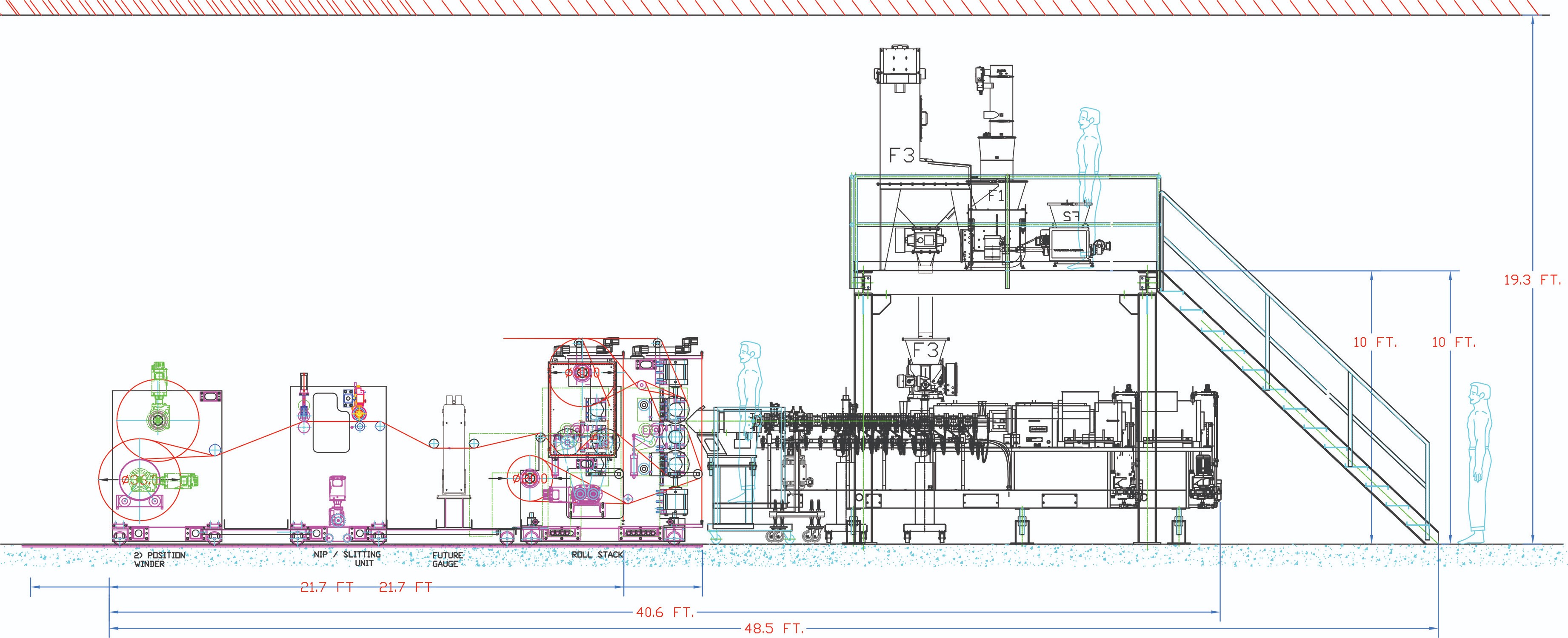

In the installation phase, you should generally start with larger machines and work toward smaller pieces. Remember not to position something large, like the power panel, so that it blocks access to another part of the line. The twin-screw extruder—in this case a 180-mm machine—is typically installed after the mezzanine and support structures.

Once a system is installed, but before it is started up, conduct a preliminary evaluation of the equipment. This will include the technical documentation (SOP, FAT) as well as operating instructions. Time should be allotted for operator-related modifications to the system.


When you are shopping for a line for compounding, devolatilization, reactive and direct extrusion, purchasing the correct equipment is only part of the equation. Not unlike an addition to your house, communication (by providing all relevant specifications) and selecting the right contractors will make all the difference in getting the project completed on time without (or at least with minimal) cost overruns. Local contractors are generally preferable.
You must be prepared to provide detailed specifications and engineering efforts up front to any companies, including machinery suppliers, that offer turnkey solutions. An organized engineering effort is required to provide an accurate turnkey system and installation proposal. A word to the wise: Don’t overly rely on third parties.


PREPARATION PHASE
Site preparation and coordination of the many divergent tasks that are required to install and successfully commission equipment is best not left to chance. Even modest advanced planning will yield benefits far beyond the installation and startup phases of a new project.
Before starting, it is highly recommended that the technical and timeline aspects of a project be defined in a written specification. Request-for-quotation and bid documents need to be thoughtfully prepared to facilitate effective communication with vendors and contractors to obtain accurate information on both performance and timeline. Using local and experienced contractors that are familiar with plant personnel and local codes, where possible, generally helps the project’s overall efficiency.
The following checklists are intended to serve as a rough guideline for what’s needed:
Engineering Documentation:
- In-house and vendor drawings prepared in AutoCAD;
- Operating manuals for all equipment;
- P & ID drawing for entire system;
- General arrangement views of entire system, plan and elevation;
- Extruder assembly drawing, three views;
- Barrel/screw layout (to scale in AutoCAD), elevation view only;
- Standard utility requirements: electrical, water, compressed air;
- System utility requirements: dust control and any special HVAC requirements;
- Wiring diagrams for extruder, feeders, and other auxiliary equipment.
Contractor Documentation:
- Sub-vendor mechanical, electrical, and installation drawings;
- Floor loading drawing;
- System interconnecting cabling drawing;
-Conduit runs;
-Number of conductors;
-Wire type and gauge, etc.; - System interconnecting piping drawing.
Additional Documentation:
- Detailed functional specification for PLC logic;
- System Input/output list;
- Source code for programming;
- Bid package preparation for third-party contractors;
- Spare-parts lists/pricing for all equipment supplied from bill of materials;
- Environmental permit applications, as required.
Factory Acceptance Test (FAT), including:
- Visual inspection and identification of system components;
- Review of control-panel layout;
- Documentation of model numbers, serial numbers, and pertinent specifications of all applicable components;
- Inspection of electrical devices and corresponding wiring;
- Confirmation of tagging and labeling;
- Heat-zone check-out;
- Identification/verification of product contact materials and surface finishes;
- Overview and demonstration of power-up procedure;
- Verification of temperatures, speeds and other indicated values;
- Complete system dry test;
- Generation, recording and compilation of FAT documentation.
INSTALLATION PHASE
This is where you find out how prepared you really are. Adequate space, light and administrative assistance may not always be available, but establishing the resources that are available will help ensure a successful completion of a project. Careful planning and implementation are the keys to success, including:
Mechanical:
All workers must have adequate PPE (Personal Protection Equipment). Generally, this includes, as a minimum, safety shoes, safety glasses, a hard hat, and work gloves. Explosion-proof and hazardous materials require special handling and treatment. Set up a “contractor area” and provide multiple copies of all the mechanical and electrical drawings. Require that all responsible parties have access to information as needed.
Create a physical “laydown area” in the plant. This area will be used to lay out the equipment as each skid is unpacked. Keep it separate from where the equipment will be installed, but not too far away. Open cardboard boxes so you can see what’s inside. Keep the parts from each supplier together. Take pictures of incoming packages and parts.
Use the general-arrangement drawing to mark the floor with the rough outline in chalk of each major piece of equipment or component.
Carefully consider the order of installation. Generally, start with larger machines and work toward smaller pieces. Remember not to position something large, like the power panel, so that it blocks access to another part of the line. The twin-screw extruder is typically installed after the mezzanine and support structures.
Rigging tip #1: Don’t lift a machine any higher than is required, and move very slowly. (Professional riggers never want a lifted load to have any momentum.)
Rigging tip #2: Know the approximate weight of each item before attempting to lift it, and never lift a load over a person (web straps and chains can break).
Don’t anchor any machinery to the concrete floor until everything is installed and it’s confirmed that all the positions and alignments are correct (an exception may be necessary for some machinery because of its size and weight distribution). Once you are satisfied that all the machinery is in the correct position, anchor the fixed machines to the floor.
Electrical: Review the field wiring specification with the electrical contractor to ensure it follows the provided cabling- and conduit-run instructions. Make note of any exceptions and document each remedy for issues that develop. Review each piece of equipment’s wiring diagram with the contractor and confirm the availability of the various types of wire and cables required.
Make sure all power is “locked out/tagged out” while the electrical work is being done. Confirm the on-site procedures. There should be absolutely no way any part of the system can be energized.
Think through which machines are fixed and which are moveable. (Example: underwater-pelletizer cart moves on floor tracks.) Make sure flexible cables and appropriate connections are planned. All interconnecting wires/cables should be marked according to the wiring diagram. Changes/corrections should be noted for the as-built configuration.
Do not apply power to the main panel or any other parts of the system until the appropriate technician is on-site and has inspected the installation.
Piping/Plumbing:
As part of preparation, the piping contractor provided a drawing (P&ID) showing all the pipe routings and sizes suited to the expected maximum flow rates. As installation progresses this document is modified accordingly. Discuss with the contractor what material will be used for the various piping runs (black iron, galvanized, stainless steel, PVC, etc.).
Confirm the location of isolation ball valves. Branches of the system will need to be shut off for maintenance. To aid in troubleshooting, consider where pressure or temperature gauges are to be located. Mark all the final information on the P&ID.
As with the electrical contractor, where machines are on tracks or will be moved for maintenance, plan on flexible connections and make a note of any required quick disconnects. If any of the piping will be carrying chilled water, those pipes should be insulated. When finished, label all piping with its purpose and arrows showing the flow direction.
Filling and Checking Fluids:
Confirm that each gearbox in the system is filled with the correct grade of oil. Make a note of the gearboxes that arrive from the factory filled with oil and establish which are sealed and will not require oil changes. (Synthetic oils are now being used and are good for the lifetime of many smaller gearboxes.)
Check to ensure all water-cooling tanks are filled. Sometimes it’s best to start with plain city water. If no leaks are apparent, then change to the recommended water with corrosion inhibitors.
Safety Check:
A safety team or OSHA team must evaluate the installation for potential hazards and confirm that issues are being addressed systematically by the site’s safety/health program. Categorize concerns as they apply to the relevant regulations and suggest remedies as required. Categories may include:
- Walking and working surfaces;
- Fire safety;
- Hazardous-material storage/handling;
- Confined-space entry (vessels and crawl spaces);
- Machine guards;
- Lock out/tag out;
- Electrical (power tools/welding equipment).
START-UP PHASE
Before any production, a preliminary evaluation of the equipment is conducted. This will include the technical documentation (SOP, FAT) as well as operating instructions. Time should be allotted for operator-related modifications to the system.
Installation Qualification:
The first thing the technician should do upon arriving on-site is to inspect the installation work.
- Visual inspection and identification of system components;
- Verification of all utility connections;
- Inspection of electrical devices and corresponding wiring;
- Heat-zone check-out;
- Overview and demonstration of power-up procedure.
The technicians should follow a start-up checklist. Beginning with the machine interlocks, the checklist will include:
- Verification of all safety devices and system interlocks;
- Verification of temperatures, speeds and other indicated values;
- Complete system dry test;
- Generation, recording, and compilation of IQ documentation;
- Mechanical items related to machinery operation.
It’s best to check the functions of the most complicated componentry (PLC/HMI, Emergency Stop, AC variable-speed drives, heat zones, etc.) before simpler items such as single-speed motors and level switches. Some motors need to be tested uncoupled, while most peripheral-system motors are safe to test coupled. It is important to confirm that the motor rotation is correct prior to running the machinery under load.
Material will be required to put an initial load on the extruder. Have plastic on-site, so the technicians can put a load on the extruder when it’s ready for an initial test. Run all the machines below 50% load at first, while checking for any abnormal sounds, vibration, fluid leaks, etc. When the technician is confident all is OK, then the system can be run up to higher rates.
Operational Qualification:
Training is the final step in starting up a new system. Once the system is working properly it’s time to tackle operator training. It’s very difficult to troubleshoot equipment issues while training people at the same time. Operator training is best handled independently after the system is up and running.
- Review customer-generated SOPs;
- Review equipment and systems manual;
- Review FAT and IQ documentation where required;
- Equipment operation conformity check-out;
- Review the normal value on the gauges, indicators and the zone controllers in a manual/discrete operator interface;
- Confirm the initial calibrations and establish a method to collect the data that will be used to maintain an operating baseline;
Review touchscreen/HMI operation:
- Access level (operator/engineer/administrator);
- Heat-up, interlock/bypass;
- Set up screen;
- Calibration screens;
- Interlocks and alarms;
- Startup checklist;
- Main screen;
- Data logging.
Review the startup procedure:
- The main disconnect;
- Temperature settings and heat-soak times;
- Startup water-cooling systems and lube-oil pumps;
- Turn on downstream equipment;
- Fill the feeders;
- Start the main drive at low speed;
- Start the feeders at low rate;
- Monitor torque;
- Engage the pelletizing equipment;
- Ramp up extruder and feeders to appropriate rate;
- Increase the pelletizer speed to match rates.
Turn on vacuum pump and/or open valve to the system.
- Review how to clear an upset condition and clean/maintain the vacuum pump.
- Monitor feed throat for feed limitations.
- Discuss various processing tips.
- Review the use of the special tools and preventive items to be noted daily, monthly, and annually.
The objective for the installation of any twin-screw extruder system is to plan well, provide an efficient, well-designed installation plan, and maintain a timeline and budget. The end-result is a fully operational and documented system. This doesn’t happen by chance. The initial specifications developed during the preparation phase of a project become a “living document.” While this up-front work can be tedious and time consuming at the beginning, it ultimately minimizes miscommunications and saves time and money.
Turnkey isn’t always turnkey. While the term may be flippantly used to describe the installation, in reality there are many responsible parties that must contribute to ensure that a twin-screw system is operational on time and producing a quality product. No matter what, it’ll be a lot of effort.
ABOUT THE AUTHORS:
Bert Elliott has held various manufacturing and engineering positions with extruder OEMs since 1981 and has been Leistritz’s engineering manager since 1993. He has been involved in over 1000 extruder installations, including many in the Far East. Contact: (908) 685-2333; belliott@leistritz-extrusion.com; leistritz-extrusion.com.
William L. Novak is the product-area manager for Leistritz Extrusion in Somerville, N.J. His responsibilities include business-development efforts to expand the use of twin-screw extrusion into new areas and applications, as well as regional responsibilities. Previously, he was Coperion’s regional service manager. During his tenure at Coperion, Novak held several sales- and engineering-related positions and has more than 27 years of product-development experience. Contact: wnovak@leistritz-extrusion.com.
Charlie Martin is president and general manager of Leistrtiz. Martin has been in the extrusion industry for more than 25 years, is a member and former chair of the SPE Extrusion Div. and has given 100+ papers at various technical conferences on a range of extrusion topics around the world. Contact: cmartin@leistritz-extrusion.com.


Related Content

LFT-D Thrives in Automotive and Other Durables
Teijin Automotive acquires its 10th direct long-fiber thermoplastic system as demand for this technology soars.
Read More
10 Ways to Improve Twin-Screw Compounding Performance
There are many techniques known to operators and plant engineers for increasing the performance of a twin-screw compounding extruder.
Read More
Green’s the Theme in Extrusion/Compounding
The drive toward circular economy is requiring processors to make more use of PCR. Machine builders at K—across all extrusion processes—will be highlighting innovations to help them do just that.
Read More
More Than a Compounder: They Have the Science to Create New Custom Materials
Insight Polymers & Compounders leverages its expertise in polymer chemistry to develop next-generation materials.
Read MoreRead Next

Processor Turns to AI to Help Keep Machines Humming
At captive processor McConkey, a new generation of artificial intelligence models, highlighted by ChatGPT, is helping it wade through the shortage of skilled labor and keep its production lines churning out good parts.
Read More
Why (and What) You Need to Dry
Other than polyolefins, almost every other polymer exhibits some level of polarity and therefore can absorb a certain amount of moisture from the atmosphere. Here’s a look at some of these materials, and what needs to be done to dry them.
Read More
Understanding Melting in Single-Screw Extruders
You can better visualize the melting process by “flipping” the observation point so that the barrel appears to be turning clockwise around a stationary screw.
Read More