
Get Better at Swapping Out Your Twin-Screw Elements
Here’s what you need to know to safely and efficiently remove, clean, restage, and reinstall your twin-screw extruder screw set.
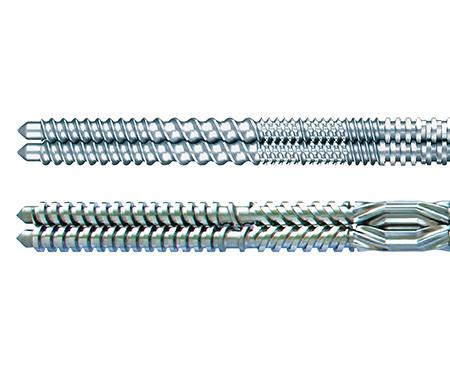
Co-rotating and counter-rotating twin screw sets.
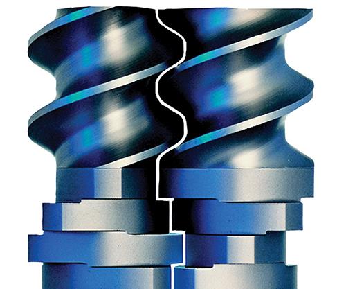
Note that there is an intermesh gap between screw elements. The tolerance between the elements is very tight, but a gap should be visible. A flashlight can be used to confirm visibility and check that the line of light running between the elements remains constant.


As compounders move from one job to the next, time is money. Twin-screw compounding extruders are all designed with removable elements whose position on the screw shaft is designed to optimize the process. And when the run ends and it’s time to move to the next one, these screw sets need to be removed and swapped out for a new set. How quickly and efficiently that essential task is carried out has direct impact on the bottom line.
With that in mind, here are best practices you should consider putting in place to expedite this process.
First—if at all possible—work on the screws immediately after use while they are still hot, or put the screw shaft assembly back in the extruder to heat the shafts and elements together. Allowing the elements time to heat up slowly (about 20 min) is always better. The idea is then to remove the screw tips and slide off a portion of the screws onto a raised table or cart right at the end of the machine.


If the shafts must be removed from the machine and heated with a torch, please use caution and heat evenly all the way around the element. Do not let the elements change color! This can affect the metallurgy. Warm them instead of burning them. Use a rosebud acetylene torch and be patient. While the elements are hot, use a punch made from wood or hard plastic to push the elements from the shaft.
An aluminum or brass drift pin can also be used, but caution is always advisable when impacting the elements. An electric impact hammer will help significantly.
Follow these steps:
• Use hot gloves.
• Support the screw-shaft assemblies at enough points so that they do not bend.
• Unscrew the tips to remove the elements.
• While using the rosebud, pull the element from the shaft.
• More difficult elements may need friendly persuasion.
• Angle the appropriate punch against the flight of the element.
• Use a rubber mallet and hammer while heating until the element moves.
• Remove one element at a time and be sure to brush clean or scrape the exposed shaft.
For difficult-to-remove elements, an impact hammer is a noisy device, but works very well at breaking loose stuck screw elements. The steps outlined above still need to be followed for screw removal, but additionally:
• Wear hearing protection.
• Modify the device to accept a brass tip.
• While heating, apply hammering action to the flight of the element.
SCREW ELEMENT CLEANING AND INSPECTION
You’ll likely get better results by at least doing an initial cleaning with a steel-wire brush or copper gauze as the screws are removed from the machine. Once they are brushed off, you can place the elements in an oven or fluidized bath to clean them. But be aware of the temperature rating of the metallurgy and don’t exceed it.
If there is black, baked-on, degraded material, some form of mechanical abrasion will be required to remove it. Brass or copper brushes are often too soft and won’t get baked-on, degraded materials off. If this is the case:
• Wear gloves and eye protection.
• Use a stiff steel-wire brush wheel on a bench grinder.
• Use a belt sander (small air-powered portable belt sanders work well).
• Use a sandblaster or dry-ice blaster.
• Clean element keyways and splined bores.
Once the elements are clean, inspect them for hairline cracks and any nicks or gouges. Nicks and gouges may become cracks and should be gently smoothed out with a file or grinding disc.
In addition, end faces should be “stoned” or sanded smooth with 320 grit sandpaper. This should be done on a level, flat mechanical surface such as a marble slab or thick steel plate. Lay emery cloth or 320 grit paper flat on the surface and work the face of the element in a figure-eight pattern, applying only enough pressure to clean the element face evenly. If wear rate is to be documented, the dimensions should be checked with a micrometer and recorded. Elements with hairline cracks should be discarded.
Damaged elements break apart while running and have been known to twist shafts, wreck barrels, and cause catastrophic failure to gearboxes.
REBUILDING THE SCREW SHAFT ASSEMBLY
Screw components have sharp edges and can cause injury if not handled properly. Leather-palm gloves or gloves made from other cut-resistant fabrics should be worn whenever handling screw elements.
Here are some additional tips:
• Clean the shafts with a wire brush to remove any remaining foreign material. This includes the coupling splines.
• Inspect the screw elements and use the above procedure to clear any foreign material.
• An anti-seize compound should be used every time elements are assembled on a shaft. A candidate is Gleitmo 820 (fuchs-lubritech.com). It is a white grease that does not degrade at high temperatures.
• Anti-seize should coat all shaft surfaces, but use it sparingly (wipe on-wipe off). Any anti-seize that builds up on an element’s end faces while installing on the shaft must be removed.
• Position both shafts as a pair parallel to each other. If the shaft clamping block is available, use this fixture to hold the shafts in the correct timing position.
• If the fixture is unavailable, clamp the shaft ends between two wood blocks at the correct shaft centerline distance.
• The screw elements will now be installed as pairs. The relative position between the screw elements and the shaft set screws must be correct (timing).
• Once the first pair is in the correct orientation, the remaining elements are arranged “face to face.” It is common to move the first pair back out toward the end of the shaft so the end profiles of each element can be aligned so they match.
• Assemble the screw elements onto the shafts following the design drawing.
• Complete the screw-shaft assembly by threading on a pair of screw tips and tightening just hand-tight for now. The final tightening will be done after the screws are in the extruder. Note: Proceed carefully, wiping the element end faces each in its turn. Be sure to double check their alignment, especially on splined shafts. This will ensure the ability of the screws to turn properly as a set and expedite the reinstallation of the completed assembly.
• The assembled screws can now be double checked by ensuring the gap between the completed assemblies is spaced consistently. The tolerance between the elements is very tight, but a gap should be visible. A flashlight can be used to confirm visibility and check that the line of light running between the elements remains constant.
• Install the screw-shaft couplings on the gearbox output shafts.
• Coat the shaft splines liberally with an anti-seize compound.As an assembly check, lay the two screws on a flat table or floor so they’re intermeshed correctly, and roll the screw set back and forth, while looking for any interferences (this applies to co-rotating screws only). A set of elements incorrectly installed will either rub together or tend to push the two screws apart where they intermesh.
REINSTALLING SCREWS IN THE EXTRUDER
To reinstall the completed screw-shaft assemblies, first ensure that the gearbox output shafts and couplings are in the correct position: On a 180°offset, this means the setscrews or coupling pointers are facing outwards at 9 and 3 o’clock . To rotate the output shafts of the gearbox, either turn the motor input coupling by hand (with the main power shut off and locked out), or rotate the motor very slowly using the drive.
Orient the screw tail shafts the same way (9 and 3 o’clock), and hold the two screws close together so they’re intermeshed. At this point:
• Remove any hardened material from the barrel bores.
• Vacuum all loose debris from connecting piping and barrel bore.
• Ensure proper alignment of the barrels.
• Visually check for possible interference from plugs, adapters, and devices.
• Insert the timed screw-shaft assembly level and parallel.
• Do not force the shafts further if an interference is felt. • Once the screw-shaft splines clear the seal plate, coat the splines with anti-seize.
• Push the shaft assembly the remaining distance into the coupling.
• Complete the screw shaft coupling installation.
Once the screws are fully engaged in the couplings, check to see that both screw tips are protruding from the barrel end flange by the same distance. If they’re not, something is wrong and the screws should be removed and the assembly checked.
At this time, do the final tightening of the screw tips using the tip wrench supplied with the machine. Remember that the tips have a left-hand thread on a co-rotating extruder. Tighten each tip until the gearbox/motor starts to rotate—that’s tight enough. Do not use any kind of “cheater pipe” on the tip wrench to torque the tips tighter.
As a final check, with the speed set point very low (1-2 rpm) start the main drive and rotate the screw set through a few revolutions. If everything seems OK, increase the speed to 20 rpm and listen for any knocking sounds. Minor clicking sounds are normal because the screws/barrels are dry. As material is introduced clicking sounds will usually go away.
ABOUT THE AUTHORS
Bert Elliott has held various manufacturing and engineering positions with extruder OEMs since 1981 and has been Leistritz’s engineering manager since 1993. Over the last 30 years, he has been involved in over 1000 extruder installations, including many in the Far East. Contact: (908) 685-2333; belliott@leistritz-extrusion.com; leistritz-extrusion.com.
William L. Novak is the product-area manager for Leistritz Extrusion in Somerville, N.J. His responsibilities include business-development efforts to expand the use of twin screw extrusion into new areas and applications, as well as regional responsibilities. Previously, he was Coperion’s regional service manager. During his tenure at Coperion, Novak held several sales and engineering related positions and has more than 27 years of product-development experience. Contact: wnovak@leistritz-extrusion.com.


Related Content

Engineering Resins Compounder Expands to Take on More Scrap
Polymer Resources responds to sustainability push by upgrading plant with grinding and shredding equipment to take on both postindustrial and postconsumer reclaim.
Read More
Sustainability Among the Many Niches at Niche Polymer
Founded in 1987, Niche Polymer continues to grow—both organically and through acquisition—by focusing its product-development efforts on ever-changing market needs. Adding value to both industrial and post-consumer scrap is a growing part of this effort.
Read More
How to Configure Your Twin-Screw Extruder: Part 3
The melting mechanism in a twin-screw extruder is quite different from that of a single screw. Design of the melting section affects how the material is melted, as well as melt temperature and quality.
Read More
More Than a Compounder: They Have the Science to Create New Custom Materials
Insight Polymers & Compounders leverages its expertise in polymer chemistry to develop next-generation materials.
Read MoreRead Next

People 4.0 – How to Get Buy-In from Your Staff for Industry 4.0 Systems
Implementing a production monitoring system as the foundation of a ‘smart factory’ is about integrating people with new technology as much as it is about integrating machines and computers. Here are tips from a company that has gone through the process.
Read More
How Polymer Melts in Single-Screw Extruders
Understanding how polymer melts in a single-screw extruder could help you optimize your screw design to eliminate defect-causing solid polymer fragments.
Read More
Troubleshooting Screw and Barrel Wear in Extrusion
Extruder screws and barrels will wear over time. If you are seeing a reduction in specific rate and higher discharge temperatures, wear is the likely culprit.
Read More