
How Does Your Molding Machine Control Pack Pressure?
It seems some new machines have pack velocity issues, as machine builders are confusing processors with controllers that are more complicated than they need to be and less user-friendly.
.jpg;width=70;height=70;mode=crop;format=webp)


With hundreds of variables that can influence your process, the last thing you need is machine-controller quirks fouling up your day. Machine controllers play a significant role in production of acceptable parts. There are subtle but significant differences among controllers; with the goal of making identical parts on different molding machines, it is c1itical that the processor understands these variations. So let’s take a close look at how machine manufacturers differ in the function of second-stage pack or hold. How different are they? Even Krusty Sr. might be surprised.
All machines follow the general sequence of injection, where the screw starts at the “shot size” and injects molten plastic at one or more velocities to a preset transfer position. At the instant the screw reaches this transfer or cutoff position, the machine switches from first (injection) stage to second (pack and hold) stage. Different machine manufactures have different options on what happens during pack and hold. Some offer time at a pressure, others offer stages of both pressure and time. Others offer stages for pressure, time, ramp times and velocities. Unfortunately this complicates injection molding processing, and in my opinion certain options are highly detrimental for consistent parts. Wondering why?


Machine manufacturers are eager to come up with more sophisticated processing modes but rarely check them out in production with cavity-pressure monitoring.
Since there are a number of options for pack and hold, depending on the machine and manufacturer, we will set constant parameters and review seven variations or options. To describe these possible options we will use the following set (constant) conditions:
1. First stage or injection: All machines are set up to inject (first stage) and transfer at a position or volume to second stage, using in this example 1 sec ± 0.04 sec of first-stage injection. Using the same mold on each machine we find that the pressure at transfer is a “plastic” pressure of 16,000 psi. For the purpose of discussion all pressures will be in “plastic” (not hydraulic) numbers. This makes comparing electric machines to hydraulic machines easier. Also, if you want identical parts, you must duplicate plastic conditions—not machine setpoints—as you take a mold from one machine to another. As popular as hydraulic pressure is with processors, it does not translate between machines due to different intensification ratios.
2. Second stage (pack/hold): Here we will program two pack pressures: 10,000 psi for 3 sec, followed by 8000 psi for 5 sec. Again, all pressures are “plastic” not hydraulic. The following hypotheticals attempt to demonstrate the possible variations within second stage between different machines:
Machine Type A: This machine allows the processor to set only one time and pressure for second-stage pack or hold. For example, pressure at 10,000 psi for 8 sec. The pressure goes from transfer pressure of 16,000 psi to 10,000 psi and holds that pressure for 8 sec. See Figure 1.
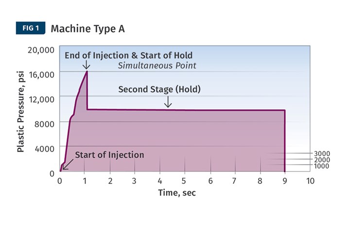
This machine allows the processor to set only one time and pressure for second-stage pack or hold.
Machine Type B: The machine allows the processor to set two or more stages of hold pressures with associated times. For example, 10,000 psi for 3 sec plus 8000 psi for 5 sec, for an 8-sec total hold time. There are multiple possible hold-pressure responses depending on the machine manufacturer:
• Machine Manufacturer 1: The pressure drops from the first-stage transfer pressure of 16,000 psi to 10,000 psi as fast as possible. At the end of the 3 sec the pressure drops immediately to 8000 psi for 5 sec. See Fig. 2 for a graphic plot of the plastic pressure vs. time.
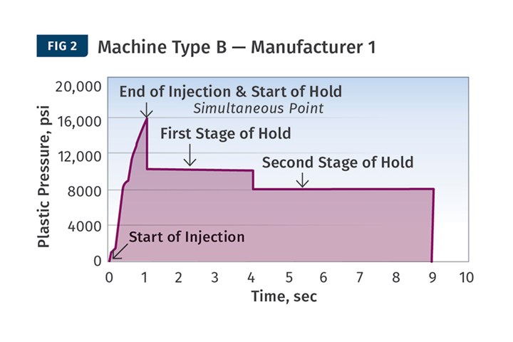
The machine allows the processor to set two or more stages of hold pressures with associated times. Here, the pressure drops from the first-stage transfer pressure of 16,000 psi to 10,000 psi as fast as possible. At the end of the programmed 3 sec, pressure drops immediately to 8000 psi for 5 sec.
• Machine Manufacturer 2: The machine takes 3 sec to ramp down from the transfer pressure of 16,000 psi to 10,000 psi and then rapidly goes to 8000 psi and holds there for 5 sec. In this case the first time is really a ramp time to the set pressure, not a time at the set pressure. See Fig. 3 for a graphic plot of plastic pressure vs. time.
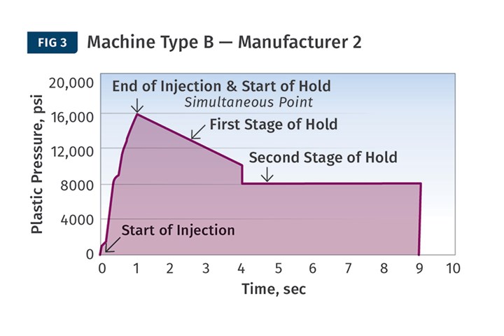
Here, the machine takes 3 sec to ramp down from the transfer pressure of 16,000 psi to 10,000 psi and then rapidly goes to 8000 psi and holds it for 5 sec. The first time is really a ramp time to the set pressure, not a time at the set pressure.
• Machine Manufacturer 3: The machine takes 3 sec to ramp down from the transfer pressure of 16,000 psi to set hold pressure of 10,000 psi and then takes 5 sec to ramp down from 10,000 psi to 8000 psi. Both hold times are “ramp times” not times at a set pressure. See Fig. 4 for a graphic plot of plastic pressure vs. time.
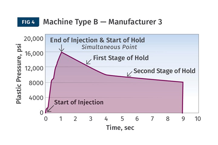
The machine takes 3 sec to ramp down from the transfer pressure of 16,000 psi to set hold pressure of 10,000 psi and then takes 5 sec to ramp down from 10,000 psi to 8000 psi. Both hold times are “ramp times,” not times at a set pressure.
Machine Type C: These machines allow the processor to set two or more stages of hold pressures, times and velocities. Using the same pressures and times as above, we will now set 35 mm/sec for the first hold-stage velocity and 15 mm/sec for the second hold-velocity stage.
• Machine Manufacturer 4: Only the first stage of hold has a velocity setting, pressure dominates both stages. The pressure ramps down from the transfer pressure of 16,000 psi to 10,000 psi at a velocity of 35 mm/sec until hold pressure of 10,000 psi is reached. At this point velocity control is lost (pressure limited) and the machine holds a constant 10,000 psi for whatever time remains of the 3 sec. At the end of the 3 sec the pressure drops rapidly to 8000 psi and holds there for 5 sec. See Fig. 5 for a graphical plot of pressures vs. time.
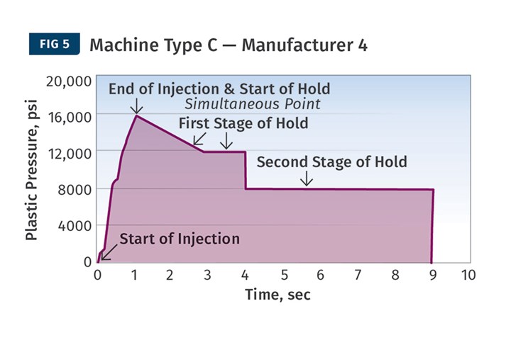
Here, pressure dominates both stages. The pressure ramps down from the transfer pressure of 16,000 psi to 10,000 psi at a velocity of 35 mm/sec until hold pressure of 10,000 psi is reached. At this point velocity control is lost (pressure limited) and the machine holds a constant 10,000 psi for whatever time remains of the 3 sec.
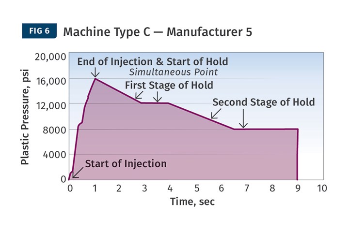
• Machine Manufacturer 5: Pressure overrides set velocities for both stages of hold. The pressure ramps down from the transfer pressure of 16,000 psi to 10,000 psi at a velocity of 35 mm/sec until pressure to drive the screw forward reaches 10,000 psi. At 10,000 psi velocity control is lost (pressure limited) and the machine holds a constant 10,000 psi until whatever time remains of the 3 sec. At the end of the 3 sec the pressure ramps to 8000 psi at a velocity of 15 mm/sec until pressure reaches 8000 psi and holds 8000 psi for whatever time is left of the preset 5 sec of hold. Again, this step is pressure limited and I doubt there would be any velocity control as the hold pressure goes from 10,000 psi to 8000 psi. See Fig. 6 for a graphical plot of pressures vs. time.
• Machine Manufacturer 6: Velocity overrides set pressures. The pressure ramps down from the transfer pressure of 16,000 psi and will be driven by velocity control to whatever pressure is required to achieve 35 mm/sec velocity for 3 sec. Velocity overrides the pressure setting and the pressure will likely not be 10,000 psi. At the end of the 3 sec the machine will go into 15 mm/sec velocity for 5 sec. Again, velocity control overrides the pressure setting. Figure 7 shows several shots under these conditions (plastic pressure in red, cavity pressure in green; (scales not identical). As can be seen my attempts to gain process consistency, after hours of trials, were not successful.
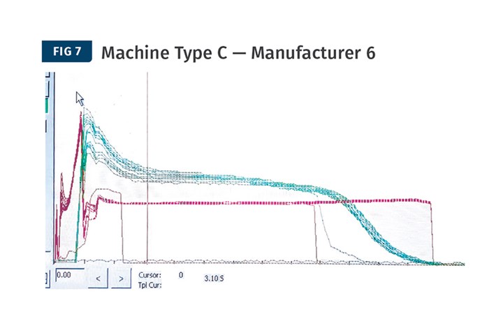
Velocity overrides set pressures. Graph shows several shots under these conditions (plastic pressure in red, cavity pressure in green; scales not identical). Attempts to gain process consistency, after hours of trials, were not successful.
Confused? Me too. This is far more complicated than it should be. Processors have enough to deal with. Machine manufacturers are eager to come up with more sophisticated processing modes but rarely check them out in production with cavity-pressure monitoring. With the new and faster computers available, programmers with good intentions are adding features—pack velocity as an example—that hinder product consistency.
Bottom line: Many machine manufacturers are making controllers more complicated than they need to be and less user-friendly by adding options of questionable value. Velocity control on pack without a pressure limit or pressure cutoff is a prime example. For evaluation of any machine controller with second-stage (pack or hold) velocity control, it is best to have cavity-pressure sensing.
Cavity-pressure data is critical in evaluating machine performance and consistency. Figure 6 provides an example. Note that the machine is fairly consistent (red curves) while cavity pressure (green curves) varies. Base performance evaluations on data not hype.
ABOUT THE AUTHOR: John Bozzelli is the founder of Injection Molding Solutions (Scientific Molding) in Midland, Mich., a provider of training and consulting services to injection molders, including LIMS, and other specialties. Contact john@scientificmolding.com; scientificmolding.com.


Related Content

The Strain Rate Effect
The rate of loading for a plastic material is a key component of how we perceive its performance.
Read More
A Simpler Way to Calculate Shot Size vs. Barrel Capacity
Let’s take another look at this seemingly dull but oh-so-crucial topic.
Read More
Why (and What) You Need to Dry
Other than polyolefins, almost every other polymer exhibits some level of polarity and therefore can absorb a certain amount of moisture from the atmosphere. Here’s a look at some of these materials, and what needs to be done to dry them.
Read More
How to Set Barrel Zone Temps in Injection Molding
Start by picking a target melt temperature, and double-check data sheets for the resin supplier’s recommendations. Now for the rest...
Read MoreRead Next

Is It Time For Injection Molding Machines to be Standardized?
If you looked at four machines from four different suppliers, you’ll find four different sets of icons and terminologies, all in different layouts.
Read More
INJECTION MOLDING: How Does Your Machine Control Pack Velocity?
You’ll need to find out in order to develop a molding process that you can repeat from machine to machine and mold to mold.
Read More
How Polymer Melts in Single-Screw Extruders
Understanding how polymer melts in a single-screw extruder could help you optimize your screw design to eliminate defect-causing solid polymer fragments.
Read More