
How Second-Stage Injection Speed Influences Your Process
As an injection molder, you’re familiar with first-stage fill-speed profiles and second-stage pressure settings, but have you considered the function of second-stage speed, or “hold flow”? Here’s what it does and how it affects your molded part.


Hold speed or hold velocity? How many machines today have it and what does it do to your process? The machine controller input of hold velocity started to become more and more prevalent with the onset of electrically driven molding machines. The setting tells the machine how fast to move the screw during second stage. But, and this is a big but, second stage is a pressure-limited portion of our process. You can’t have velocity control on a pressure-limited portion of a process. So how effective is the speed setting, then?
The molding machine will use the speed that is input into the machine controller only until the set second-stage pressure has been reached. Once your second-stage pressure is reached, you will notice that the screw slows down and may even eventually stop. We look at this velocity input as a matter of response time. The setting is telling the machine controller how fast you want to get to the second-stage pressure setting.


So, the question becomes, “How does this setting impact my process?” The answer to that is simple: Yes.
Below you will find a couple of graphs that represent the injection-pressure profile and the part weight correlated with seven different second-stage velocities, starting at 5 cm3/sec up to 35 cm3/sec moving in 5 cm3/sec increments. Setting speeds in volumetric units rather than linear units of mm/sec or in./sec has been available on machines sold in the last 10-15 years, and it has become more popular with molders because it translates speed profiles directly between machines with different screw sizes, etc.
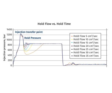
FIG 1 Hold flow, or second-stage velocity, affects the amount of time it takes to reach holding-pressure setpoint.
In Fig. 1, you will see that the slowest speed is represented in orange. It shows a large droop in the injection-pressure profile after transfer has been reached. The reason this occurs is that the cavity is short at transfer, and it takes time before the cavity completely fills and starts to pressurize. The resistance in the cavity is now pushing back on the screw, and the second-stage pressure setting is reached and stabilized. As the second-stage velocity, or “hold flow,” is increased, you will notice that the droop gets smaller and smaller, and the time it takes to reach the second-stage pressure setpoint gets shorter and shorter.
In Fig. 2, part weight is plotted against the second-stage speed setting. You will notice that the part weight continues to rise until 30 cm3/sec is reached. You will also notice that at this time any additional second-stage speed has no influence on the part weight. This is the sweet spot for where the second-stage speed should be set—at a point where the final part weight is no longer influenced by the second-stage speed.
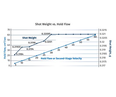
FIG 2 The point where part weight levels off is the correct setting for hold flow, or second-stage velocity.
Remember to think about what is happening to the plastic and to your parts during this time. This is one of the most influential phases of your process for setting the part dimensions. The slower the speed and response are, the slower you are packing out the parts, and therefore allowing the material to cool and solidify.
What About Other Machines?
If you are like most molders who are scheduling a mold in several different molding machines, it will be important to understand how each of those machines reacts to the second-stage speed setting. Just because 30 cm3/s works on machine #4 doesn’t mean that you will get the same response on machine #12. This could be due to different machine makes and models, ages of the machines, hydraulic vs. electric drive, you name it. There are too many things to list that could contribute to the difference.
You may also have machines that don’t have an input for second-stage velocity—many machines out there don’t. In this case, the molding machine will typically use the last fill-speed input on the machine controller. If that setting is slow, then the second-stage velocity will also be slow.
Other Influences
Besides the second-stage speed setting, the size of the fill-only part can also contribute to the droop, or slow response. If the fill-only part is 60% full at transfer instead of 98%, then it will take more time for the cavity to fill out and pressurize. When conducting this type of study, we want to make sure that the parts are 98% full at transfer to eliminate that as a potential cause in the response. We want to make sure that we are measuring only the influence of the second-stage speed on the process.
Ultimately, we are trying to produce the most repeatable parts in the fastest, most repeatable time, and the second-stage speed setting is an often-overlooked influence on the process. Knowing how your machines respond to this input is one more step toward being better than the next molder.
About the Author: Shane Vandekerkhof joined RJG in 2003 as a member of the Customer Support team. He was soon qualified to conduct on-site training for RJG customers in the use of RJG’s software and equipment. After two years, Shane took on the role of business development for Europe where he was responsible for creating new accounts, supporting existing accounts, and working with sales representatives. Shane became one of RJG’s trainer/consultants in 2007, teaching RJG Systematic Molding and Master Molder courses. In 2018, Shane became the global education & training integrator, responsible for maintaining and implementing standard training and consulting practices across the globe.


Related Content

How to Get Rid of Bubbles in Injection Molding
First find out if they are the result of trapped gas or a vacuum void. Then follow these steps to get rid of them.
Read More
What to Do About Weak Weld Lines
Weld or knit lines are perhaps the most common and difficult injection molding defect to eliminate.
Read More
How to Set Barrel Zone Temps in Injection Molding
Start by picking a target melt temperature, and double-check data sheets for the resin supplier’s recommendations. Now for the rest...
Read MoreRead Next

Troubleshooting Screw and Barrel Wear in Extrusion
Extruder screws and barrels will wear over time. If you are seeing a reduction in specific rate and higher discharge temperatures, wear is the likely culprit.
Read More
How Polymer Melts in Single-Screw Extruders
Understanding how polymer melts in a single-screw extruder could help you optimize your screw design to eliminate defect-causing solid polymer fragments.
Read More
People 4.0 – How to Get Buy-In from Your Staff for Industry 4.0 Systems
Implementing a production monitoring system as the foundation of a ‘smart factory’ is about integrating people with new technology as much as it is about integrating machines and computers. Here are tips from a company that has gone through the process.
Read More