
How to Collect & Interpret Process Data in Extrusion
The first installment of this three-part series focuses on proper use of a data- acquisition system.
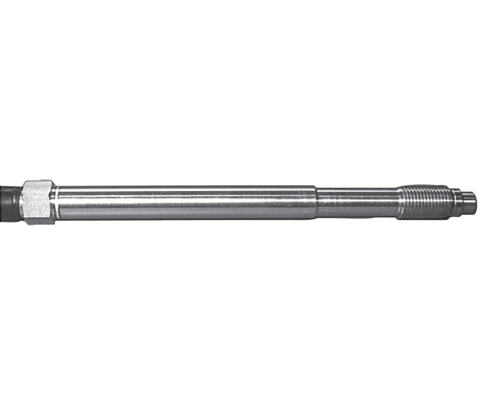
For pressure measurement, the author prefers optical transducers because of their robust design. Photo: FOS
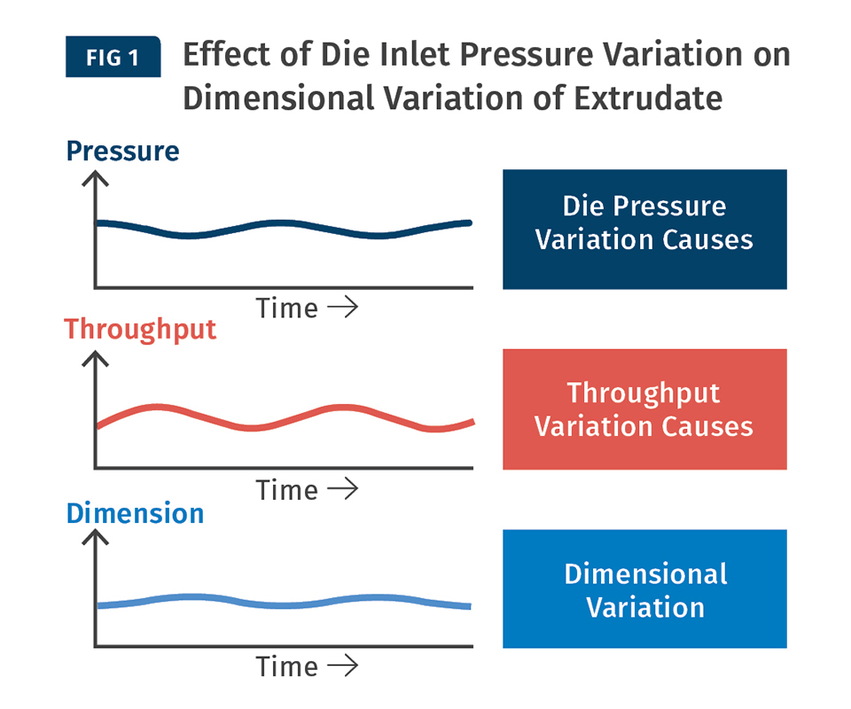
Variation of die inlet pressure causes variation in flow rate; this, in turn, will cause dimensional variation of the extruded product.
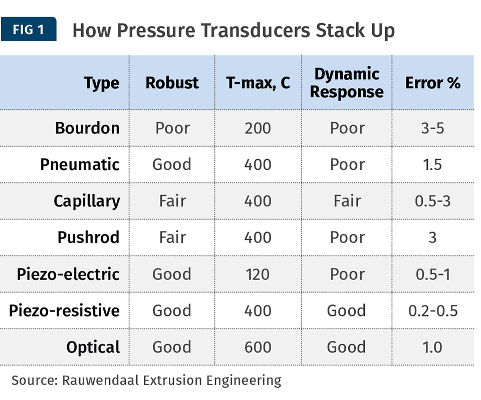
Source: Rauwendaal Extrusion Engineering
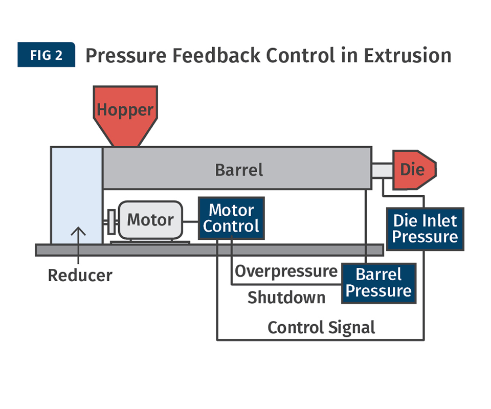
At a very minimum, pressure should be measured at two locations: before and after the breaker plate. With pressure-feedback control, the screw speed is adjusted such that the pressure after the breaker plate (die inlet pressure) remains constant.
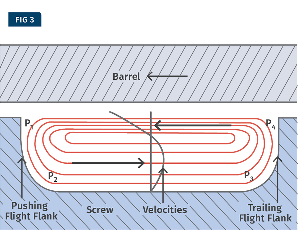
Flow in a cross-section of the screw channel in the metering section of the extruder.
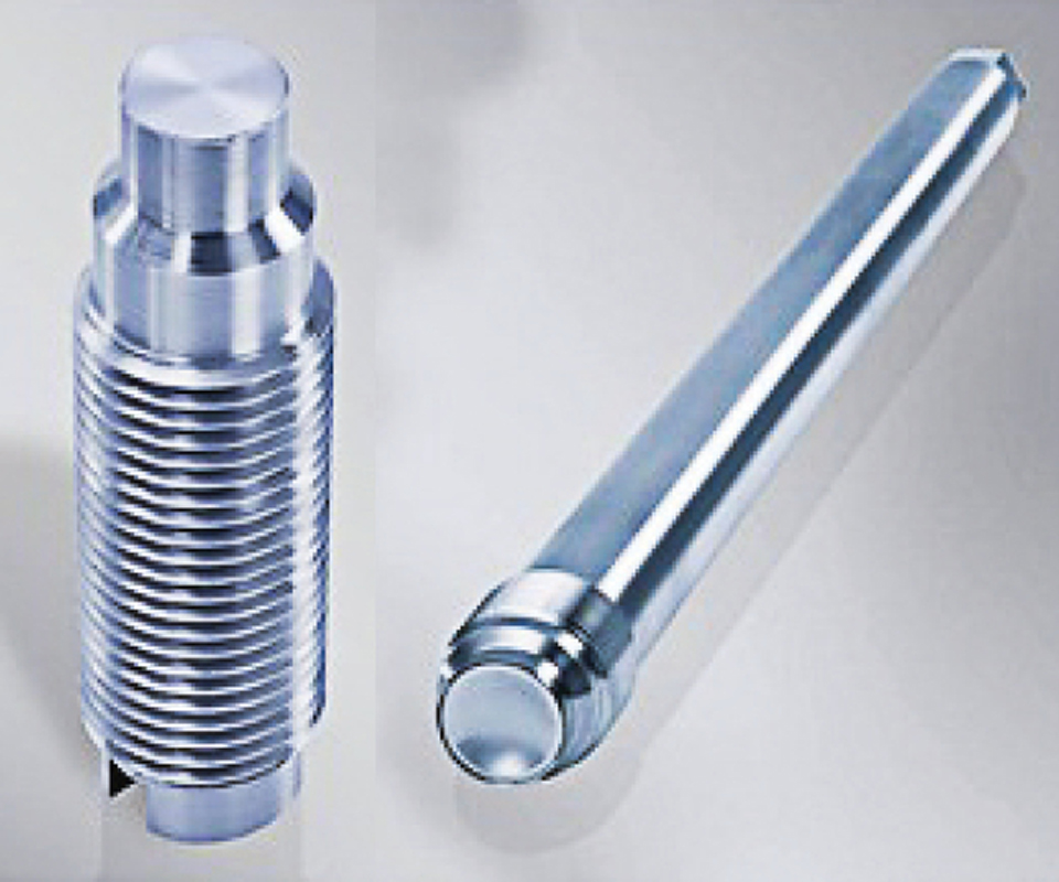
The rupture disk is typically place in the extruder barrel just before the breaker plate and screen pack, where the highest pressure is likely to occur. (Source: Striko)
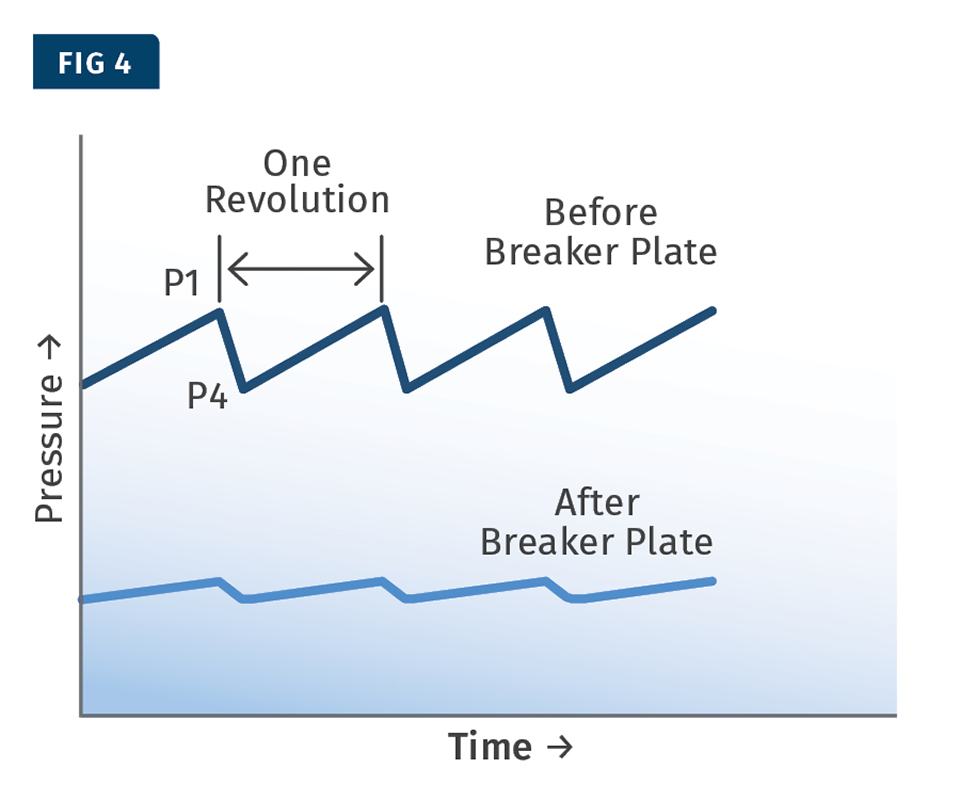
When pressure is measured in the metering section of the extruder, it will have a saw-tooth pattern.
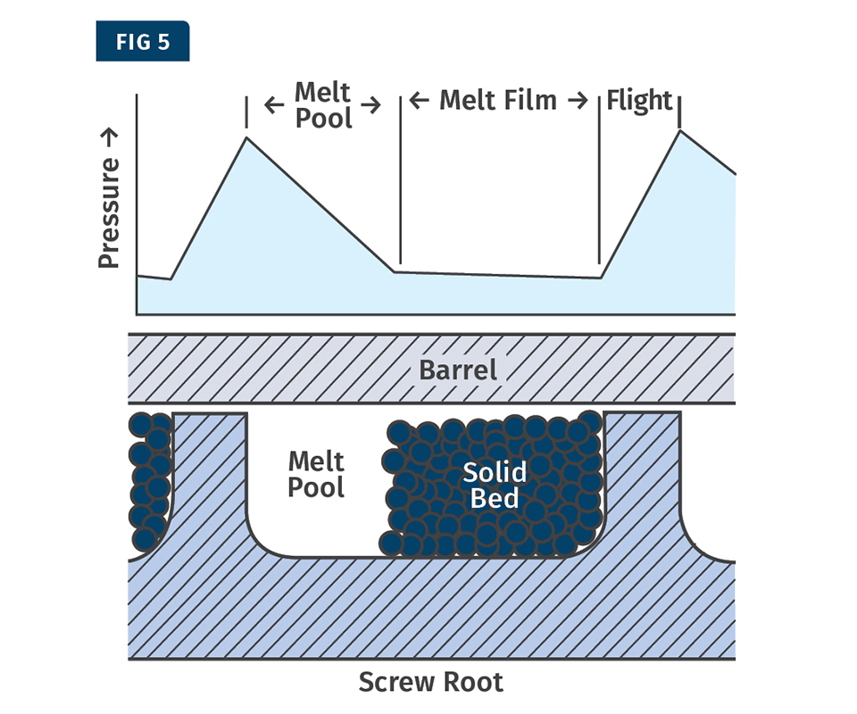
The pressure gradient in the melt film will be different from the pressure gradient in the melt pool. Therefore, when pressure is measured midway along the barrel, the pressure pattern reflects the location of the solid bed, the melt pool, and the flight. By locating several pressure transducers along the length of the barrel, the progress of melting along the length of the extruder can be analyzed.


Many extrusion lines sold nowadays are equipped with data- acquisition systems (DAS). These systems can present extruder operators and process engineers with large amounts of data. There are several critical issues in the proper use of a DAS, which are the focus of this article, part one in a three-part series:
1. Are the correct process variables measured and monitored?
2. Are these process variables measured correctly?
3. Is the data-collection rate appropriate?
4. Are operating personnel capable of properly interpreting the data?
VITAL SIGNS OF THE
EXTRUSION PROCESS
The three most important extrusion process variables are melt pressure (P), melt temperature (T), and motor load (I). These three process variables represent the vital signs of the extruder. When the extruder is not functioning correctly one, two, or all three of these variables will show abnormal behavior. It is no coincidence that these three process variables are analogous to the vital signs of the human body: blood pressure, body temperature, and pulse. The human body functions because the heart pumps blood through our vascular system. Blood pressure and pulse are measures of how well our blood is being pumped. In extrusion P, T, and I are measures of the pumping efficiency of the extruder.
One of the most important process measurements is the specific energy consumption (SEC). This is the motor power divided by the throughput. In the U.S. the SEC is typically expressed in units of hp.hr/lb; elsewhere it’s more commonly expressed in kW.hr/kg.
The SEC is a measurement of the amount of energy from the motor introduced into the polymer. As a result, the SEC is closely related to the increase in stock temperature in the extrusion process. Higher levels of SEC lead to higher melt temperatures.
The minimum SEC needed to extrude a polymer is determined by its thermal properties. It is the resin’s specific heat multiplied by the temperature rise in the extrusion process—the increase in enthalpy. For semi-crystalline polymers, the minimum SEC value is about 0.10 hp.hr/lb, or about 0.16 kW.hr/kg. It is good practice to monitor the SEC because it is a good measure of the energy efficiency of the extrusion process. If the SEC in a single-screw extrusion process is above 0.2 hp.hr/lb (0.32 kW.hr/kg), this indicates poor energy efficiency and will likely result in high melt temperatures.
MELT PRESSURE IS KING
The most important process variable is melt pressure. Die inlet pressure is a direct measure of the flow rate through the die. Variation of die inlet pressure causes variation in flow rate; this, in turn, will cause dimensional variation of the extruded product (see Fig. 1). A graphical display of die inlet pressure versus time provides a clear picture of the process stability—or lack thereof. A simple display of pressure (analog or digital) is much less useful.
When an operator looks at a digital pressure readout with numbers typically changing 10 times or more per second, it is impossible to get a clear picture of the pattern. The human mind has very limited ability to analyze large numbers of numerical data. On the other hand, when the operator can look at a graph of pressure versus time, the trend of the pressure pattern becomes immediately obvious. The human mind has remarkable ability to interpret graphical information. For this reason trend plots are a very important element of a good DAS.
Pressure is measured with a pressure transducer. These have a thin diaphragm that contacts the molten plastic. Increasing melt pressure will deflect this diaphragm, and this deflection is a measure of the amount of pressure acting on the diaphragm. There are several different types of pressure transducers. The accompanying table lists several types with a comparison of their robustness, maximum temperature, dynamic response, and error.
Many strain-gage capillary pressure transducers are filled with mercury. Clearly, this is a safety concern. The diaphragm of a capillary pressure transducer is quite thin, usually from 0.100 to 0.125 mm—about the thickness of a 20 weight sheet of paper. As a result, the diaphragm is easily damaged. When the diaphragm of a mercury-filled pressure transducer ruptures, the liquid will enter into the workplace and contaminate the product. For that reason mercury-filled transducers should not be used for medical and food-packaging extrusion.
It is worth noting that the capillary pressure transducer is the most commonly used transducer in the extrusion industry. But from a technical perspective, the capillary pressure transducer, in my view, is not the best; in fact, it is not even second best. Considering that pressure measurement is the most important variable in the extrusion process, it is surprising that the most commonly used pressure transducer is one that has some clear deficiencies.
At a very minimum, pressure should be measured at two locations: before and after the breaker plate. Usually a screen pack is placed against the breaker plate to capture contaminants and to make sure that these contaminants do not end up in the extruded product. As contamination builds up on the screen pack, resistance to flow increases and extruder output will drop. This, of course, will reduce the extrudate dimensions. To counteract this problem a pressure-feed- back control is typically used. In this control, the pressure after the screen pack and breaker plate is measured and controlled by the screw speed (see Fig. 2).
When contamination builds up on the screen pack, the pressure after the breaker plate will reduce. With pressure-feedback control, the screw speed is adjusted so that the pressure after the breaker plate (die inlet pressure) remains constant. Pressure-feedback control has been available in extruders for decades. It is also used when the extruder is equipped with a gear pump—in this case, the inlet pressure of the gear pump is controlled by the screw speed.
One limitation of pressure-feedback control is that it can only act on very slow changes in pressure—changes occurring over 10 min or longer. Pressure-feedback control cannot reduce short-term pressure variations because the control loop is too slow. However, there are several other methods that can be used to reduce short-term pressure variation.
With pressure-feedback control there is a gradual increase in screw speed and the pressure just before the screen pack and breaker plate. This pressure is often referred to as the barrel pressure. When the screw speed increases, the viscous heating in the extruder increases and will generally result in an increase in melt temperature. It is important to understand that pressure-feedback control will result in changes in the extrusion process—in particular, melt temperature. Changes in melt temperature can affect the properties of the extruded product even if product dimensions do not change.
When contamination on the screen pack builds up rapidly, this can affect the extrusion process significantly. This problem can be avoided to a large extent by using a continuous screen changer.
It is also important to have an overpressure shutdown, as shown in Fig. 2. This is a critical safety feature because under certain circumstances pressures can increase very rapidly—much faster than an extruder operator can act to shut down the extruder. Excessive pressures can cause the die to blow off the extruder in an explosive manner. Clearly, this is a problem one should avoid. For this reason, over- pressure shutdown is an important safety feature. Another important safety feature is a rupture disk. This is typically placed in the extruder barrel just before the breaker plate and screen pack, where the highest pressure is likely to occur.
For proper process analysis and troubleshooting, it is very helpful to have pressure transducers along the length of the extruder. Unfortunately, this is rare in the extrusion industry. Without pressure transducers along the barrel, the ability to troubleshoot extrusion problems effectively is substantially diminished.
When the extruder is teamed with a gear pump, it is very helpful when two pressure transducers are located downstream of the pump some distance apart. With this setup the melt viscosity in the polymer line can be easily determined. The gear-pump speed is a direct measure of the volumetric flow rate. The shear rate in the line is determined from the flow rate and the geometry of the flow channel. The shear stress can be determined from the difference in pressure between the two pressure transducers. The melt shear viscosity is simply the ratio of shear stress and shear rate. Such a setup provides real-time monitoring of the melt viscosity at minimal cost.
PRESSURES INSIDE
THE EXTRUDER
The pressures inside the extruder reflect the flow that occurs in the extruder. Figure 3 shows the flow in a cross-section of the screw channel in the metering section of the extruder. At the top of the channel there is a drag flow toward the pushing flight flank, and the pressure increases from P4 at the trailing flight flank to P1 at the pushing flight flank. At the pushing flight flank, material will move toward the root of the screw by pressure flow. As a result, pressure P1 will be greater than pressure P2 at bottom left of the screw channel in Fig. 3. At the lower portion of the screw channel, material will move to the trailing flank of the flight by pressure flow because pressure P2 is greater than pressure P3. There is pressure flow along the trailing flank of the flight because pressure P3 is greater than pressure P4.
The highest pressure in the channel is pressure P1 and the lowest pressure is pressure P4. This is the pressure drop across the flight. This pressure drop ΔPx (P1-P4) can be expressed as follows for a Newtonian fluid:
∆Px = 6μvbWxcosφ H2
In this expression, μ is the melt viscosity, vb is the barrel velocity, Wx is the width of the channel, φ is the flight helix angle, and H is the depth of the channel. The pressure drop ΔPx depends on the viscosity, screw geometry, and screw speed. When the screw geometry and screw speed are known, the viscosity can be determined from the pressure drop ΔPx.
When pressure is measured in this part of the extruder, it will have a saw-tooth pattern as shown in Fig. 4. The time between peaks equals the time for one screw revolution for a single-flight screw. This means that the screw speed can be determined from the pressure trend. A double-flighted screw will exhibit two pressure peaks for each revolution of the screw.
The pressure pattern in the melting zone of the extruder will be different because the screw channel is not only filled with molten polymer but also unmelted polymer. In a single-screw extruder, melting usually occurs by contig- uous solids melting or CSM.
In contiguous solids melting, the solid particles are compressed together in a solid bed (see Fig. 5). The solid bed forms a helical solid ribbon that wraps around the screw. As melting progresses, the size of the solid bed reduces, while, at the same time, the size of the melt pool increases. There is a thin melt film between the solid bed and the barrel. Most melting takes place at the interface between the solid bed and the melt film.
If pressures are measured in the melting zone, the pattern will be different from the melt-conveying zone. The pressure gradient in the melt film will be different from the pressure gradient in the melt pool, as shown in Fig. 5. Therefore, when pressure is measured midway along the barrel, the pressure pattern reflects the location of the solid bed, the melt pool, and the flight. By locating several pressure transducers along the length of the barrel, the progress of melting along the length of the extruder can be analyzed.
ABOUT THE AUTHOR: Dr. Chris Rauwendaal is a well-known author, lecturer, researcher, entrepre- neur, and consultant in the field of extrusion. He holds numerous patents and has written more than 200 articles and seven books related to extrusion, mixing, injection molding, and statistical process control. A Fellow of the Society of Plastics Engineers (SPE), he is the developer of the CRD, VIP, and ASM mixing technologies that utilize strong elongational flow to improve mixing in extrusion and molding. Rauwendaal also developed the HHT (high heat transfer) extruder screw designed to improve cooling in foam tandem and other extrusion operations. In 1990 he founded and is still president of Rauwendaal Extrusion Engineering. Contact: (530) 269-1082; chris@rauwendaal.com; rauwendaal.com.


Related Content

Why (and What) You Need to Dry
Other than polyolefins, almost every other polymer exhibits some level of polarity and therefore can absorb a certain amount of moisture from the atmosphere. Here’s a look at some of these materials, and what needs to be done to dry them.
Read More
How to Set Barrel Zone Temps in Injection Molding
Start by picking a target melt temperature, and double-check data sheets for the resin supplier’s recommendations. Now for the rest...
Read More
PBT and PET Polyester: The Difference Crystallinity Makes
To properly understand the differences in performance between PET and PBT we need to compare apples to apples—the semi-crystalline forms of each polymer.
Read More
How to Stop Flash
Flashing of a part can occur for several reasons—from variations in the process or material to tooling trouble.
Read MoreRead Next

Troubleshooting Screw and Barrel Wear in Extrusion
Extruder screws and barrels will wear over time. If you are seeing a reduction in specific rate and higher discharge temperatures, wear is the likely culprit.
Read More
People 4.0 – How to Get Buy-In from Your Staff for Industry 4.0 Systems
Implementing a production monitoring system as the foundation of a ‘smart factory’ is about integrating people with new technology as much as it is about integrating machines and computers. Here are tips from a company that has gone through the process.
Read More